Piping—Heating Boilers
All high points should be vented. Purge valves and a bypass valve should be installed. A boiler installed above radiation level must be provided with a low water
The boiler piping system of a hot water heating boiler connected to heating coils located in air handling units where they may be exposed to circulating refrigerated air, must be equipped with flow control valves or other automatic means to prevent gravity circulation of the boiler water during the cooling cycle. It is highly recom- mended that the piping be insulated.
Three-Way Valves
Valves designed to blend water temperatures or reduce water circulation through the boiler should not be used. Raypak boilers are high recovery low mass boilers not subject to thermal shock. Raypak offers a full line of electric sequencers that produce direct reset of boiler water temperature. Refer to the Controls Section in our Complete Catalog.
Domestic Hot Water Piping
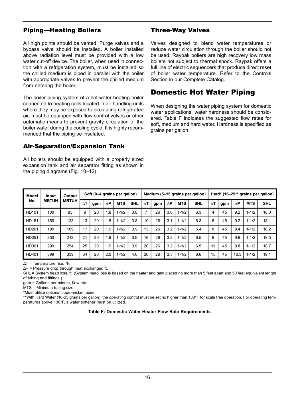
When designing the water piping system for domestic water applications, water hardness should be consid- ered. Table F indicates the suggested flow rates for soft, medium and hard water. Hardness is specified as grains per gallon.
Air-Separation/Expansion Tank
All boilers should be equipped with a properly sized expansion tank and air separator fitting as shown in the piping diagrams (Fig.
|
|
|
|
|
| ||||||||||||
Model | Input | Output | Soft | Medium | Hard* | ||||||||||||
No. | MBTUH | MBTUH |
|
|
|
|
|
|
|
|
|
|
|
|
|
|
|
∆T | gpm | ∆P | MTS | SHL | ∆T | gpm | ∆P | MTS | SHL | ∆T | gpm | ∆P | MTS | SHL | |||
HD101 | 100 | 85 | 9 | 20 | 1.8 | 3.8 | 7 | 26 | 3.0 | 6.3 | 4 | 45 | 9.2 | 18.0 | |||
HD151 | 150 | 128 | 13 | 20 | 1.8 | 3.8 | 10 | 26 | 3.1 | 6.3 | 6 | 45 | 9.2 | 18.1 | |||
HD201 | 199 | 169 | 17 | 20 | 1.9 | 3.9 | 13 | 26 | 3.2 | 6.4 | 8 | 45 | 9.4 | 18.2 | |||
HD251 | 250 | 213 | 21 | 20 | 1.9 | 3.9 | 16 | 26 | 3.2 | 6.5 | 9 | 45 | 9.6 | 18.5 | |||
HD301 | 299 | 254 | 25 | 20 | 1.9 | 3.9 | 20 | 26 | 3.2 | 6.5 | 11 | 45 | 9.8 | 18.7 | |||
HD401 | 399 | 339 | 34 | 20 | 2.0 | 4.0 | 26 | 26 | 3.3 | 6.6 | 15 | 45 | 10.3 | 19.1 | |||
∆T = Temperature rise, °F.
∆P = Pressure drop through heat exchanger, ft.
SHL = System head loss, ft. (System head loss is based on the heater and tank placed no more than 5 feet apart and 50 feet equivalent length of tubing and fittings.)
gpm = Gallons per minute, flow rate. MTS = Minimum tubing size.
*Must utilize optional
**With Hard Water
Table F: Domestic Water Heater Flow Rate Requirements
16