Manuals
/
Raypak
/
Household Appliance
/
Boiler
Raypak
HD101, HD401 operating instructions
Models:
HD101
HD401
1
37
48
48
Download
48 pages
21.74 Kb
34
35
36
37
38
39
40
41
<
>
Troubleshooting
Install
Tankstat As Shown In The Diagram Above
Maintenance
Venting Configurations
High Limit Manual Reset
Blower Adjustment
dry cleaning/laundry areas and establishments
Time/Temperature Relationships in Scalds
Safety
Page 37
Image 37
37
Page 36
Page 38
Page 37
Image 37
Page 36
Page 38
Contents
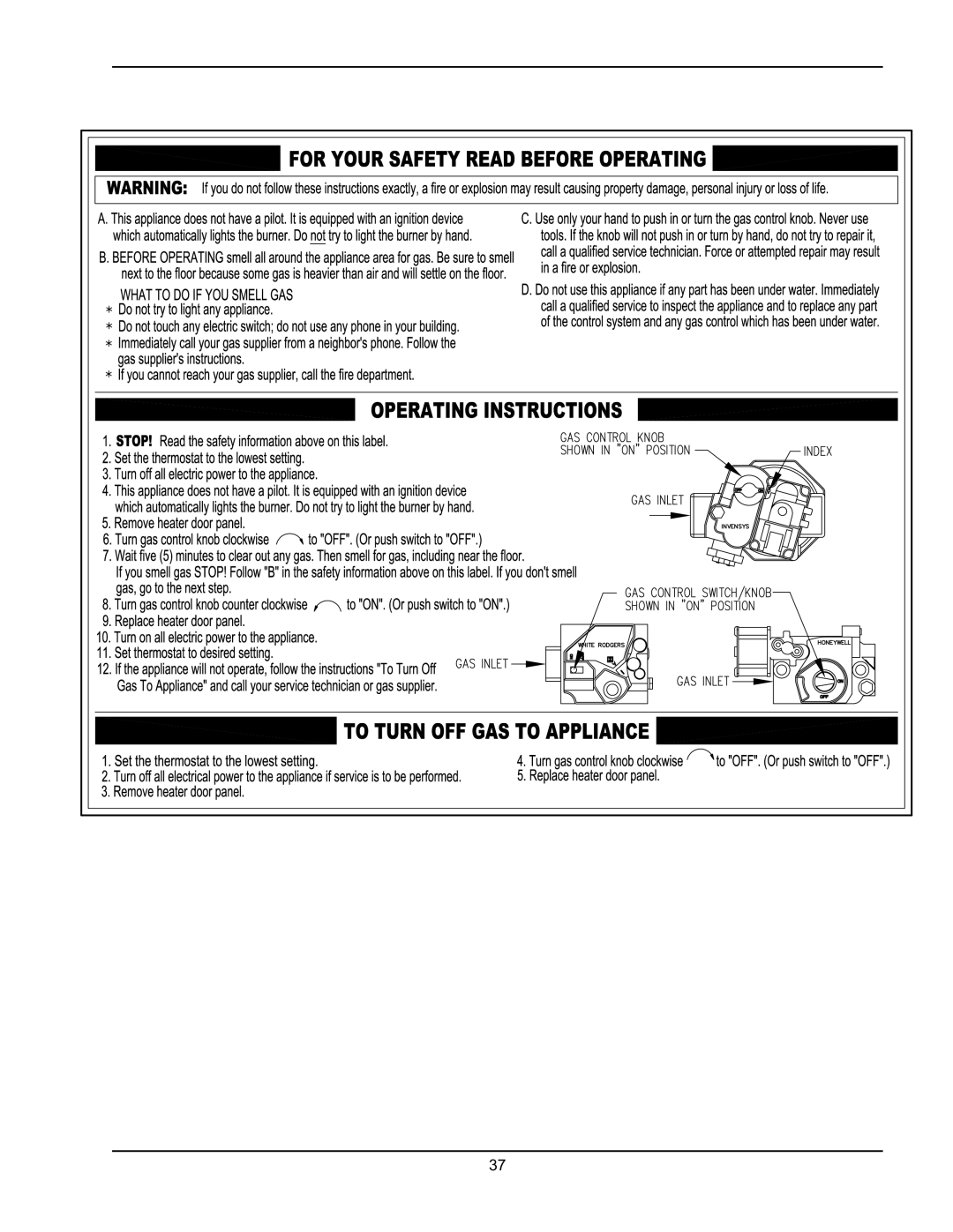
Do not try to light any appliance
WHAT TO DO IF YOU SMELL GAS
INSTALLATION & OPERATING INSTRUCTIONS
Models HD101-HD401 Types H & WH
Deletions None
Rev. 3 reflects the following
BEFORE INSTALLATION
CONTENTS
GENERAL SAFETY
INSTALLATION
DANGER
WARNINGS - Pay Attention to These Terms
WARNING - CALIFORNIA PROPOSITION
Installations at Elevation
BEFORE INSTALLATION
Product Receipt
Model Identification
Fig. 1 Component Locations - Angle View
Component Locations
Fig. 2 Component Locations - Left Side
Quantity of Burners
General Information
Vent Size in
Flue
Time/Temperature Relationships in Scalds
GENERAL SAFETY
Installation Codes
INSTALLATION
Indoor/Closet Installations
Equipment Base
Outdoor Installations
Combustion and Ventilation Air
U.S. Installations
Conventional Combustion Air Supply
Combustion Air Filter
Water Piping
Installations in Canada
General
Relief Valve Piping
Reversing Water Connections
Temperature & Pressure Gauge
Low Temperature System
Hydronic Heating
Hydrostatic Test
Page
Piping-HeatingBoilers
Domestic Hot Water Piping
Three-WayValves
Air-Separation/ExpansionTank
Gas Supply Connection
Gas Supply
Gas Pressure Regulator
Electrical Power Connections
Gas Supply Pressure
Surge Protection
Check the Power Source
Making the Electrical Connections
Table H Maximum Equivalent Pipe Length
TANKSTAT AS SHOWN IN THE DIAGRAM ABOVE
Electrical Connections — Domestic Hot Water
SINGLESTAGE TANKSTAT
CONNECTION
General
Venting
Support of Vent Stack
Barometric Damper
Vent Terminal Location
Canadian Installations2
U.S. Installations1
Table J Vent/Air Inlet Termination Clearances
Installations in Canada
US Installations
Venting Configurations
Venting Installation Tips
Natural Draft Vertical Vent Termination
Certified
Appliance
Category
inches
Horizontal Thru-wallDirect Vent Termination
Model
Model
Vertical Direct Vent System Installation
Outdoor Installation
Vertical Direct Vent Termination
High Limit - Auto Reset Optional
High Limit Manual Reset
Modulating Temperature Control Optional
CONTROLS
High and Low Gas Pressure Switches Optional
Flow Switch
Low Water Cut Off Optional
WIRING DIAGRAM-MODELS HD101-HD401
Step Step Step Step
HD101-HD401Troubleshooting
Step Step Step
Step Step Step
PRE-START-UP
Check Power Supply
INITIAL START-UP
Filling System-HeatingHeaters
Page
Gas Valve Adjustment
Main Burner Adjustment
Blower Adjustment
Start-Up
Gas Type Conversion on Valve
Safety Inspection
Follow-Up
POST START-UPCHECK
Air Filter Inspection/Removal
Heat Exchanger Removal
Maintenance Schedule
MAINTENANCE
Suggested Minimum
Yearly Beginning of each heating
Inside Combustion Air Contamination
APPENDIX
Daily
Monthly
dry cleaning/laundry areas and establishments
Areas causing contaminated combustion air
hydrochloric acid/muriatic acid
cements and glues
248 CMR 5.082a1 through
Page