Chapter 6: Additional Information
| INPUT |
| OUTPUT |
|
|
|
|
|
|
|
|
|
|
|
|
| |
|
|
|
|
|
|
| COMPONENT |
|
|
|
|
|
|
|
| VIDEO OUTPUT | |
|
| COMPOSITE |
|
|
|
| Y |
|
|
| VIDEO |
|
|
|
|
|
|
|
|
|
|
|
| DIGITAL AUDIO | Pb |
|
|
|
|
|
|
|
|
| |
RF ANTENNA/CABLE | L | AUDIO | L |
|
|
| Pr |
|
INPUT |
|
|
|
| PROG. | |||
|
|
|
|
|
| COAXIAL |
| SCAN |
| R |
| R |
|
|
|
| |
|
| IR SAT | OPTICAL | ON | OFF | |||
|
|
|
| |||||
|
|
|
|
|
|
| ||
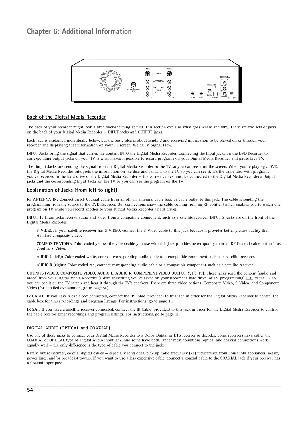
Back of the Digital Media Recorder
The back of your recorder might look a little overwhelming at first. This section explains what goes where and why. There are two sets of jacks on the back of your Digital Media Recorder — INPUT jacks and OUTPUT jacks.
Each jack is explained individually below, but the basic idea is about sending and receiving information to be played on or through your recorder and displaying that information on your TV screen. We call it Signal Flow.
INPUT Jacks bring the signal that carries the content INTO the Digital Media Recorder. Connecting the Input jacks on the DVD Recorder to corresponding output jacks on your TV is what makes it possible to record programs on your Digital Media Recorder and pause Live TV.
The Output Jacks are sending the signal from the Digital Media Recorder to the TV so you can see it on the screen. When you’re playing a DVD, the Digital Media Recorder interprets the information on the disc and sends it to the TV so you can see it. It’s the same idea with programs you’ve recorded to the hard drive of the Digital Media Recorder — the correct cables must be connected to the Digital Media Recorder’s Output jacks and the corresponding Input Jacks on the TV so you can see the program on the TV.
Explanation of Jacks (from left to right)
RF ANTENNA IN: Connect an RF Coaxial cable from an
INPUT 1: These jacks receive audio and video from a compatible component, such as a satellite receiver. INPUT 2 jacks are on the front of the Digital Media Recorder.
COMPOSITE VIDEO: Color coded yellow, the video cable you use with this jack provides better quality than an RF Coaxial cable but isn’t as good as
AUDIO L (left): Color coded white, connect corresponding audio cable to a compatible component such as a satellite receiver.
AUDIO R (right): Color coded red, connect corresponding audio cable to a compatible component such as a satellite receiver.
OUTPUTS (VIDEO, COMPOSITE VIDEO, AUDIO L, AUDIO R, COMPONENT VIDEO OUTPUT Y, Pb, Pr): These jacks send the content (audio and video) from your Digital Media Recorder (a disc, something you’ve saved on your Recorder’s hard drive, or TV programming) OUT to the TV so you can see it on the TV screen and hear it through the TV’s speakers. There are three video options: Composite Video,
IR CABLE: If you have a cable box connected, connect the IR Cable (provided) to this jack in order for the Digital Media Recorder to control the cable box for timer recordings and program listings. For instructions, go to page 11.
IR SAT: If you have a satellite receiver connected, connect the IR Cable (provided) to this jack in order for the Digital Media Recorder to control the cable box for timer recordings and program listings. For instructions, go to page 11.
DIGITAL AUDIO (OPTICAL and COAXIAL)
Use one of these jacks to connect your Digital Media Recorder to a Dolby Digital or DTS receiver or decoder. Some receivers have either the COAXIAL or OPTICAL type of Digital Audio Input jack, and some have both. Under most conditions, optical and coaxial connections work equally well — the only difference is the type of cable you connect to the jack.
Rarely, but sometimes, coaxial digital cables — especially long ones, pick up radio frequency (RF) interference from household appliances, nearby power lines, and/or broadcast towers. If you want to use a less expensive cable, connect a coaxial cable to the COAXIAL jack if your receiver has a Coaxial input jack.
54