Connections & Setup
How to Connect: Dolby Digital Receiver + Speakers
If you own a Dolby Digital® or PCM
You might want to switch INTERNAL SPEAKER SOURCE to EXT AMP and connect the audio receiver’s CENTER SPEAKER OUTPUT to the TV’s EXT AMP input to use the TV’s internal speakers as a center speaker.
•Go to Audio menu and select Audio Select if your receiver can decode DD and PCM.
•Go to Audio menu and select PCM if your receiver can decode only PCM.
How to Connect: A/V Amplifier/Receiver + Speakers
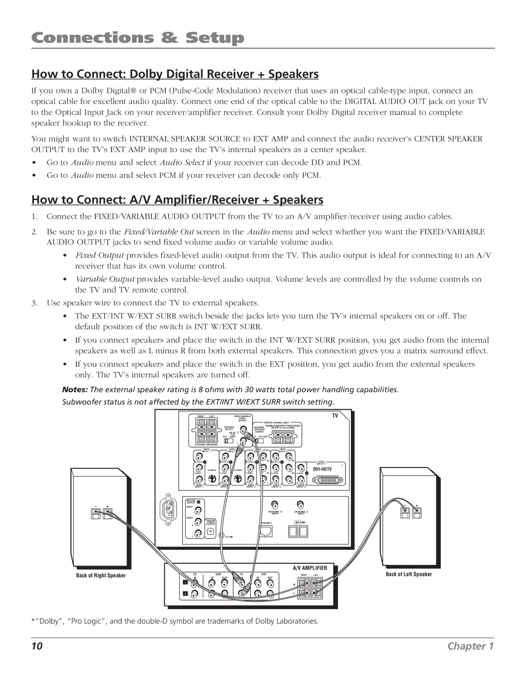
1.Connect the FIXED/VARIABLE AUDIO OUTPUT from the TV to an A/V amplifier/receiver using audio cables.
2.Be sure to go to the Fixed/Variable Out screen in the Audio menu and select whether you want the FIXED/VARIABLE AUDIO OUTPUT jacks to send fixed volume audio or variable volume audio.
•Fixed Output provides
•Variable Output provides
3.Use speaker wire to connect the TV to external speakers.
•The EXT/INT W/EXT SURR switch beside the jacks lets you turn the TV’s internal speakers on or off. The default position of the switch is INT W/EXT SURR.
•If you connect speakers and place the switch in the INT W/EXT SURR position, you get audio from the internal speakers as well as L minus R from both external speakers. This connection gives you a matrix surround effect.
•If you connect speakers and place the switch in the EXT position, you get audio from the external speakers only. The TV’s internal speakers are turned off.
Notes: The external speaker rating is 8 ohms with 30 watts total power handling capabilities.
Subwoofer status is not affected by the EXT/INT W/EXT SURR switch setting.
–+
RIGHT | LEFT |
| FIXED/VARIABLE |
|
|
|
| TV | ||
|
|
|
| AUDIO |
|
|
|
|
| |
|
|
|
| OUTPUT | CENTER CHANNEL INPUT |
|
| |||
|
|
|
|
|
|
|
| |||
|
| SPEAKER |
| INTERNAL | MAXIMUM AMPLIFIER POWER RATING | |||||
|
|
|
| (60 WATTS into 8 OHMS) | ||||||
|
| SELECT |
| SPEAKER |
|
|
|
| ||
|
|
| INT W/ | R | SOURCE |
|
|
|
| |
|
| EXT | EXT |
| TV | EXT AMP |
|
|
| |
|
| SURR |
|
|
|
| ||||
EXTERNAL SPEAKERS |
|
| L |
|
|
|
|
|
| |
|
|
|
|
|
|
|
|
| ||
VIDEO |
| VIDEO |
| VIDEO |
| VIDEO |
|
| ||
INPUT 1 |
| INPUT 2 |
| INPUT 3 |
| INPUT 4 |
|
| ||
V |
| V |
|
| V |
| PR | V | PR | VIDEO |
|
|
|
|
|
|
|
|
|
| INPUT 5 |
|
| L/MONO |
| PB |
| PB | ||||
L/MONO |
| L/MONO |
|
|
| L/MONO | L/MONO | |||
R |
| R |
|
| R |
| Y | R | Y | R |
AUDIO |
| AUDIO |
| AUDIO |
|
| AUDIO |
| AUDIO | |
INPUT 1 |
| INPUT 2 |
| INPUT 3 |
|
| INPUT 4 |
| INPUT 5 | |
RECORD |
|
|
|
|
|
|
|
|
|
|
OUTPUT |
|
|
|
|
|
|
|
|
|
|
VIDEO |
|
|
|
|
|
|
|
|
|
|
|
|
|
|
|
|
| ANTENNA B |
| ANTENNA A | |
|
|
|
|
|
|
|
| INPUT |
| INPUT |
AUDIO | DIGITAL |
|
|
|
|
|
|
|
|
|
|
|
|
|
|
|
|
|
|
| |
| AUDIO |
|
|
|
| ETHERNET |
|
| ||
R | OUTPUT |
|
|
|
|
|
| |||
|
|
|
|
|
|
|
|
| ||
L |
|
|
|
|
|
|
|
| ||
–+
Back of Right Speaker
CD
IN
L |
R |
TAPE
IN OUT
TV IN
A/V AMPLIFIER
VCR | RIGHT | LEFT |
IN | OUT |
|
+
–
Back of Left Speaker
*“Dolby”, “Pro Logic”, and the
10 | Chapter 1 |
