Connections & Setup
How to Connect: TV + Speakers
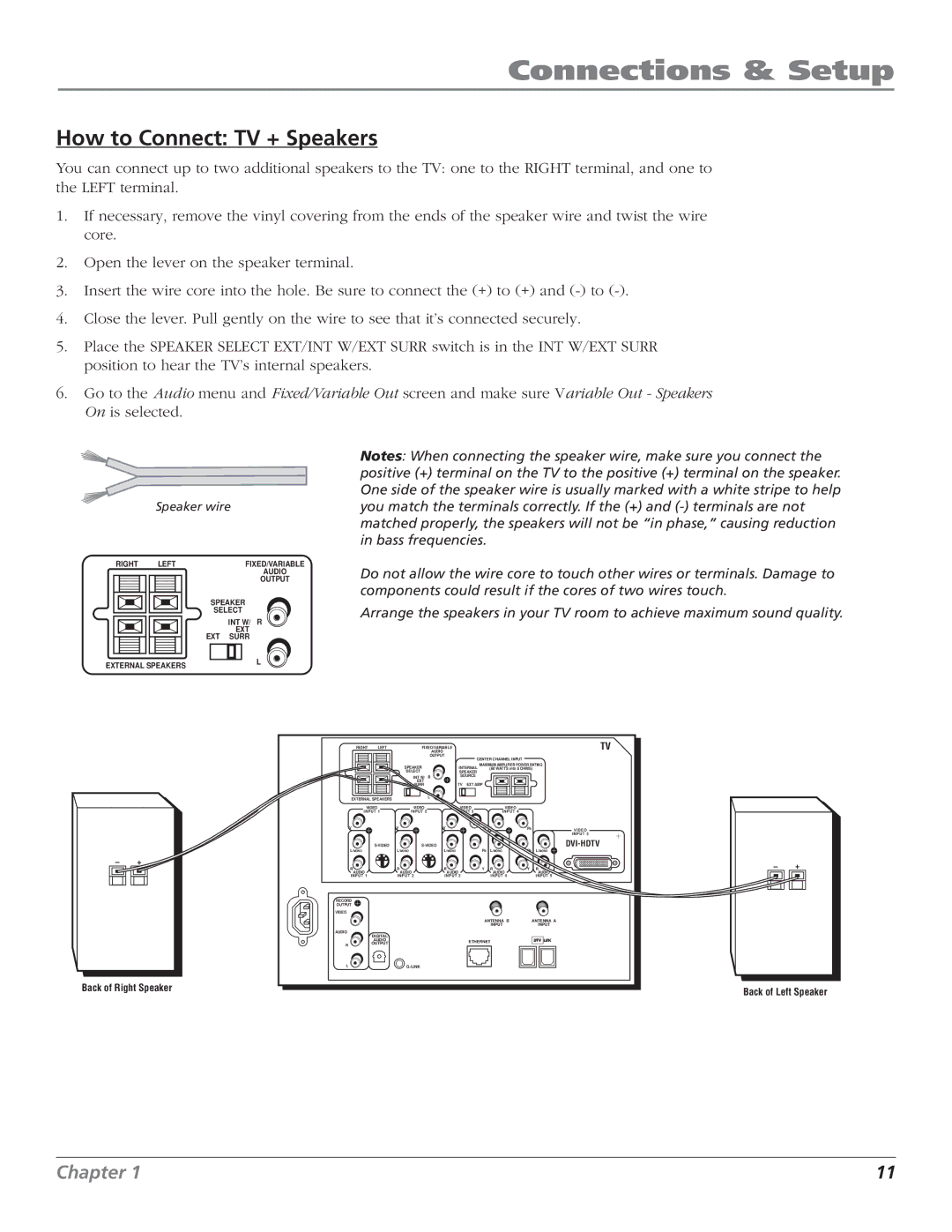
You can connect up to two additional speakers to the TV: one to the RIGHT terminal, and one to the LEFT terminal.
1.If necessary, remove the vinyl covering from the ends of the speaker wire and twist the wire core.
2.Open the lever on the speaker terminal.
3.Insert the wire core into the hole. Be sure to connect the (+) to (+) and
4.Close the lever. Pull gently on the wire to see that it’s connected securely.
5.Place the SPEAKER SELECT EXT/INT W/EXT SURR switch is in the INT W/EXT SURR position to hear the TV’s internal speakers.
6.Go to the Audio menu and Fixed/Variable Out screen and make sure Variable Out - Speakers On is selected.
Speaker wire
RIGHT | LEFT | FIXED/VARIABLE |
|
| AUDIO |
|
| OUTPUT |
| SPEAKER | |
| SELECT | |
|
| INT W/ R |
| EXT | EXT |
| SURR | |
Notes: When connecting the speaker wire, make sure you connect the positive (+) terminal on the TV to the positive (+) terminal on the speaker. One side of the speaker wire is usually marked with a white stripe to help you match the terminals correctly. If the (+) and
Do not allow the wire core to touch other wires or terminals. Damage to components could result if the cores of two wires touch.
Arrange the speakers in your TV room to achieve maximum sound quality.
EXTERNAL SPEAKERS |
| L |
–+
Back of Right Speaker
RIGHT | LEFT |
| FIXED/VARIABLE |
|
|
|
| TV | ||
|
|
|
| AUDIO |
|
|
|
|
| |
|
|
|
| OUTPUT | CENTER CHANNEL INPUT |
|
| |||
|
|
|
|
|
|
|
| |||
|
| SPEAKER |
| INTERNAL | MAXIMUM AMPLIFIER POWER RATING | |||||
|
|
|
| (60 WATTS into 8 OHMS) | ||||||
|
| SELECT |
| SPEAKER |
|
|
|
| ||
|
|
| INT W/ | R | SOURCE |
|
|
|
| |
|
| EXT | EXT |
| TV | EXT AMP |
|
|
| |
|
| SURR |
|
|
|
| ||||
EXTERNAL SPEAKERS |
|
| L |
|
|
|
|
|
| |
|
|
|
|
|
|
|
|
| ||
VIDEO |
| VIDEO |
| VIDEO |
| VIDEO |
|
| ||
INPUT 1 |
| INPUT 2 |
| INPUT 3 |
| INPUT 4 |
|
| ||
V |
| V |
|
| V |
| PR | V | PR | VIDEO |
|
|
|
|
|
|
|
|
|
| INPUT 5 |
|
| L/MONO |
| PB |
| PB | ||||
L/MONO |
| L/MONO |
|
|
| L/MONO | L/MONO | |||
R |
| R |
|
| R |
| Y | R | Y | R |
AUDIO |
| AUDIO |
| AUDIO |
|
| AUDIO |
| AUDIO | |
INPUT 1 |
| INPUT 2 |
| INPUT 3 |
|
| INPUT 4 |
| INPUT 5 | |
RECORD |
|
|
|
|
|
|
|
|
|
|
OUTPUT |
|
|
|
|
|
|
|
|
|
|
VIDEO |
|
|
|
|
|
|
|
|
|
|
|
|
|
|
|
|
| ANTENNA B |
| ANTENNA A | |
|
|
|
|
|
|
|
| INPUT |
| INPUT |
AUDIO | DIGITAL |
|
|
|
|
|
|
|
|
|
|
|
|
|
|
|
|
|
|
| |
| AUDIO |
|
|
|
| ETHERNET |
|
| ||
R | OUTPUT |
|
|
|
|
|
| |||
|
|
|
|
|
|
|
|
| ||
L |
|
|
|
|
|
|
|
| ||
–+
Back of Left Speaker
Chapter 1 | 11 |
