Clearances to Combustibles
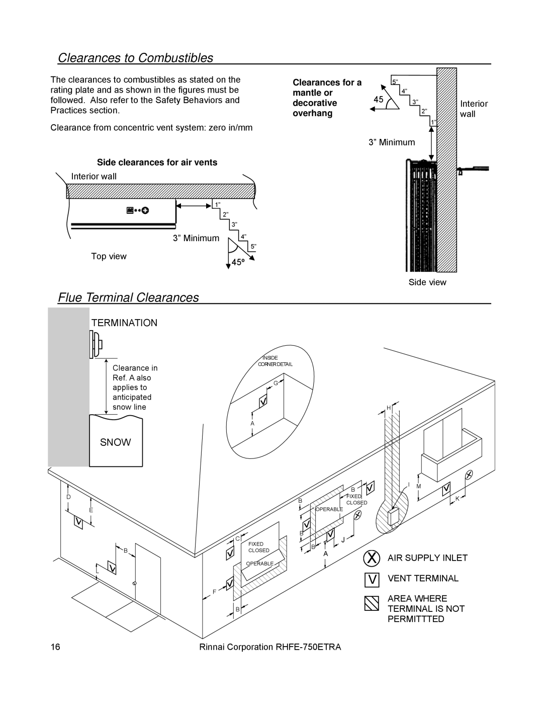
The clearances to combustibles as stated on the rating plate and as shown in the figures must be followed. Also refer to the Safety Behaviors and Practices section.
Clearance from concentric vent system: zero in/mm
Side clearances for air vents
Interior wall
![]() 1”
1”
2”
3”
|
|
|
|
|
|
|
|
|
| 3” Minimum |
|
|
| 4” |
|
| |
Top view |
|
|
|
| 5” | |||
|
|
|
|
|
| |||
|
|
|
|
|
| |||
| 45º |
|
|
| ||||
|
|
|
|
|
|
| ||
Clearances for a |
|
| 5” |
|
|
|
|
|
mantle or |
|
|
| 4” |
|
|
|
|
45 |
|
|
|
|
|
| ||
decorative |
|
|
|
| 3” |
|
| |
overhang |
|
|
|
|
|
| 2” |
|
|
|
|
|
|
| |||
|
|
|
|
|
|
|
1”
3” Minimum
Side view
Interior wall
Flue Terminal Clearances
TERMINATION
Clearance in Ref. A also applies to anticipated snow line
INSIDE
CORNER DETAIL
G![]()
![]()
H ![]()
![]()
SNOW
D
E
![]() B
B
L
A
C
FIXED
CLOSED
![]() OPERABLE
OPERABLE
F![]()
![]()
![]()
![]()
![]()
B ![]()
|
| B |
B |
| FIXED |
| CLOSED | |
| OPERABLE |
|
B | J |
|
|
| |
| B | X |
| A | |
|
|
V
![]() I M
I M
K ![]()
AIR SUPPLY INLET
VENT TERMINAL
AREA WHERE TERMINAL IS NOT PERMITTTED
16 | Rinnai Corporation |
