Connections
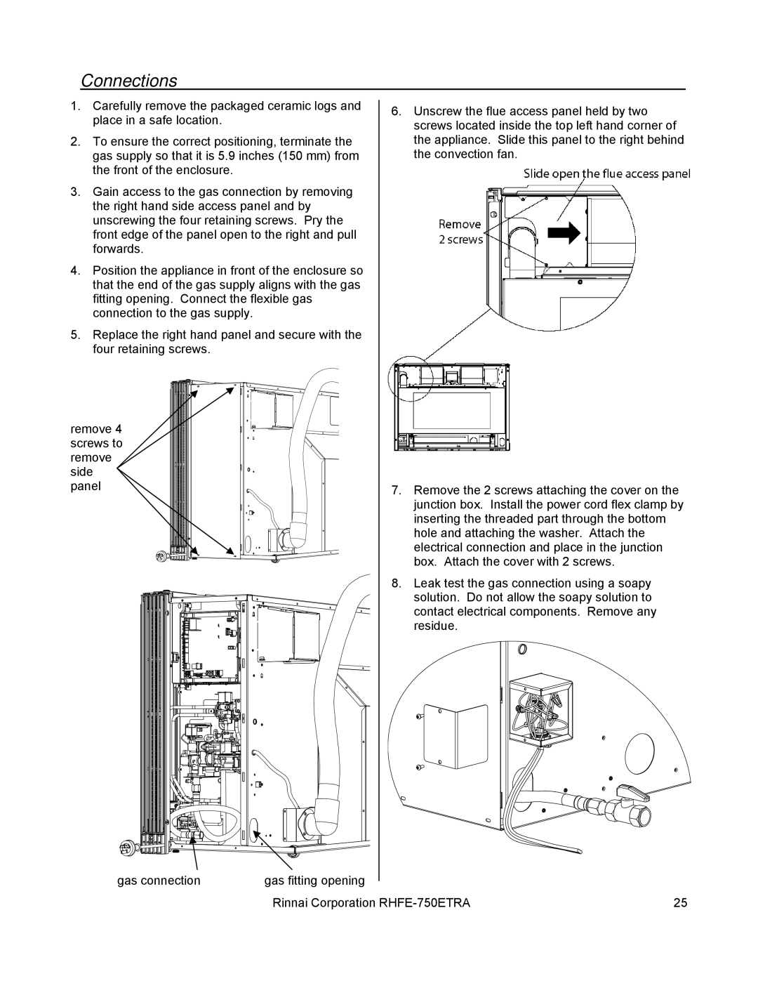
1. | Carefully remove the packaged ceramic logs and | 6. Unscrew the flue access panel held by two |
| place in a safe location. | |
| screws located inside the top left hand corner of | |
|
| |
2. | To ensure the correct positioning, terminate the | the appliance. Slide this panel to the right behind |
| gas supply so that it is 5.9 inches (150 mm) from | the convection fan. |
| the front of the enclosure. |
|
3.Gain access to the gas connection by removing the right hand side access panel and by unscrewing the four retaining screws. Pry the front edge of the panel open to the right and pull forwards.
4.Position the appliance in front of the enclosure so that the end of the gas supply aligns with the gas fitting opening. Connect the flexible gas connection to the gas supply.
5.Replace the right hand panel and secure with the four retaining screws.
remove 4 screws to remove side panel
7. Remove the 2 screws attaching the cover on the junction box. Install the power cord flex clamp by inserting the threaded part through the bottom hole and attaching the washer. Attach the electrical connection and place in the junction box. Attach the cover with 2 screws.
8. Leak test the gas connection using a soapy solution. Do not allow the soapy solution to ![]() contact electrical components. Remove any
contact electrical components. Remove any
residue.
gas connection | gas fitting opening |
|
| Rinnai Corporation | 25 |
