Venting
There are 2 categories for venting:
I.Venting with Flue Manifolds
II. Extended Venting - horizontal and vertical terminations with a maximum 33 feet and 3 elbows.
I.Venting with Flue Manifolds FOT-203 and FOT-204
The following flue manifold sizes are available:
Name | Kit No. | fits walls |
Vent Kit A | 4 1/3 - 9 1/2 inch | |
|
| (110 - 240 mm) |
Vent Kit B | 9 1/2 - 15 3/4 inch | |
|
| (240 - 400 mm) |
|
|
|
Flue extensions are not authorized to be used with the
Drilling Flue and Gas Supply Holes
Check for water and gas pipes as well as electric cables. Use the template supplied to mark the wall locations for the flue manifold and the gas supply. Drill the flue hole using a 3 1/2 inch (90 mm) drill.
For weatherboard walls, drill through the center of the weatherboard from the outside first and then through the plasterboard.
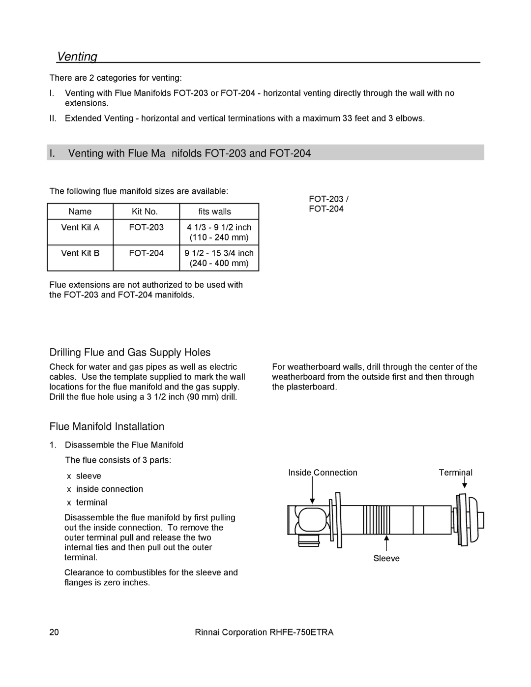
Flue Manifold Installation
1. Disassemble the Flue Manifold The flue consists of 3 parts:
• | sleeve | Inside Connection | Terminal |
|
|
• inside connection
•terminal
Disassemble the flue manifold by first pulling |
|
out the inside connection. To remove the |
|
outer terminal pull and release the two |
|
internal ties and then pull out the outer |
|
terminal. | Sleeve |
Clearance to combustibles for the sleeve and flanges is zero inches.
20 | Rinnai Corporation |