Manuals
/
Roberts Gorden
/
Household Appliance
/
Gas Heater
Roberts Gorden
CGTH-40 Cover Cap and Regulator Screw Outlet Pressure Tap, Pressure Testing
Models:
CGTH-40
CGTH-50
CGTH-30
1
41
58
58
Download
58 pages
49.39 Kb
38
39
40
41
42
43
44
45
<
>
Specifications
Install
Parts list
Connection Diagram
Thermostat Placement
Warranty
Dimension
Horizontal Venting Configurations
Heater Assembly
Testing
Page 41
Image 41
SECTION 8: O
PERATION
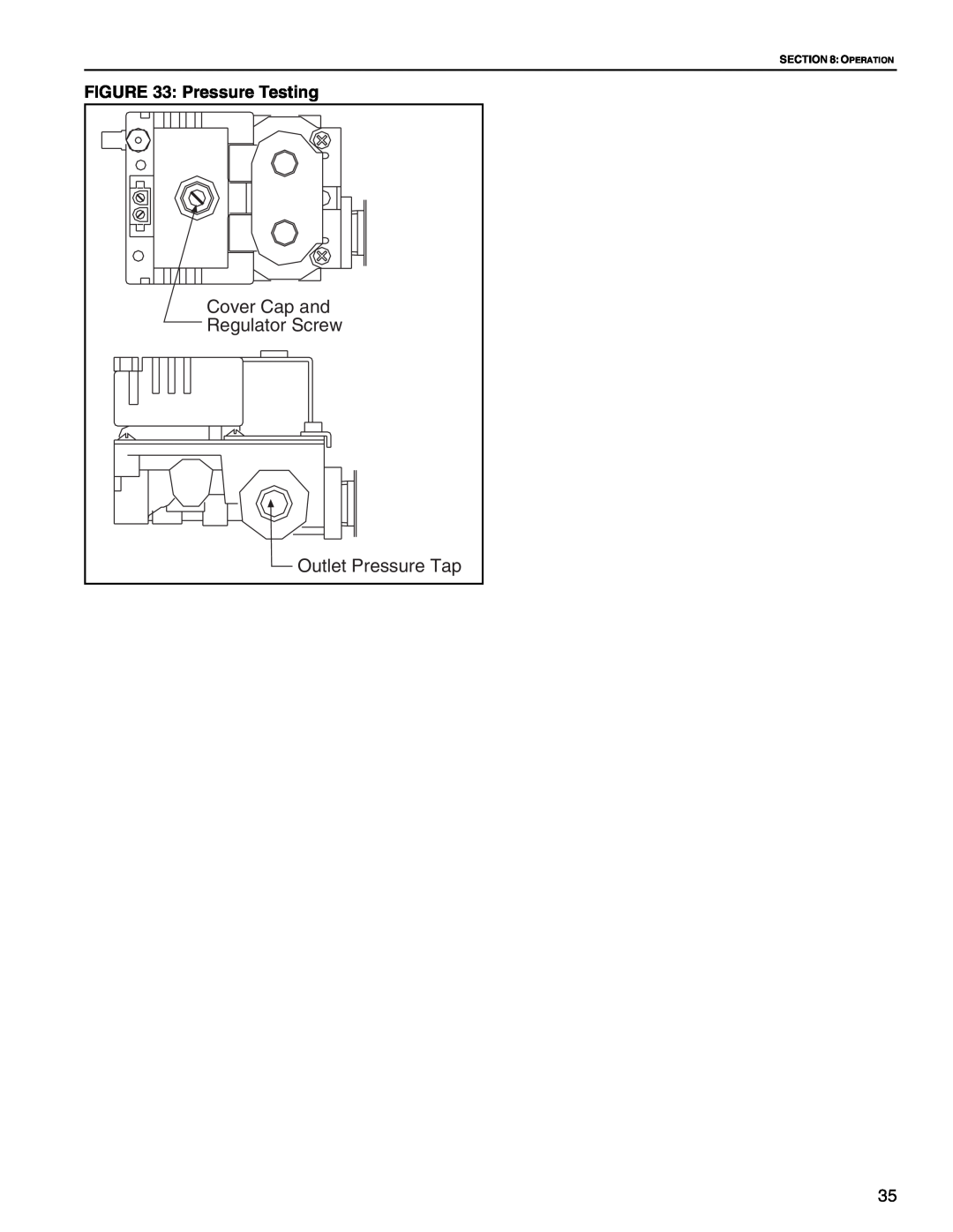
FIGURE 33: Pressure Testing
Cover Cap and
Regulator Screw
Outlet Pressure Tap
35
Page 40
Page 42
Page 41
Image 41
Page 40
Page 42
Contents
Gas-Fired, Low-Intensity
Installation, Operation
Infrared Heaters for
Residential Garages and
Page
2005
TABLE OF CONTENTS
Page
TABLE OF FIGURES
Page
Roberts-Gordon,LLC
SECTION 1 BEFORE YOU BEGIN 1.1 Read This Manual
1.2 Questions, Comments or Suggestions
2.2 About the Heater
2.3.2 Safety
Heater Assembly
available as an accessory under kit part numbers
Heater Assembly
Manual Gas
Shut-offValve
2.6 Available Accessories for Galvanized Vent
Wall Venting Kit P/N 08032200 includes
2.7Available Accessories for Cox Geelen Vent
Roof Venting Kit P/N 08032100 includes
Nipple 3/8”
HEATER SPECIFICATIONS Electrical
Inputs and Dimensions
VENTING SPECIFICATIONS Vent/Flue
Gas Inlet Connection
2.11Where Cant the Heater Be Installed?
2.10 Where Can the Heater Be Installed?
2.12 Installers Responsibility
Residential applications, such as garages
3.2.3 Meter and Service
3.2Gas Service Requirements 3.2.1 Gas Type
3.3 Electrical Service Requirements
SECTION 3 PLANNING 3.1 General
3.4.2 Venting Codes
3.4Venting Requirements 3.4.1 System Requirements
3.4.3 Balanced Flue Construction
FIGURE 3 Balanced Flue
3.5.3 Hazardous Locations
4.1 Safety Equipment
SECTION 4 INSTALLATION
4.2 Installation Tools
4.3 Installation Materials
4.5 General Venting Guidelines
4.6 Required Safe Distances from Combustibles
FIGURE 4 Horizontal Installations
All dimensions are from the reflector
FIGURE 5 45 Tilted Installations
24 Min. 609 mm
FIGURE 8 Heater Assembly
4.9 Heater Assembly
4.7 Hang the Heater
FIGURE 7 Suspension Details
FIGURE 9 Typical Installation
4.10 Typical Installation
X Dimension
4.12 Horizontal Installation
FIGURE 11 45 Tilted Installation
FIGURE 10 Horizontal Installation
4.13 45 Tilted Installation
FIGURE 12 Silicone Cap Installation
4.14 Grille Installation for Select Models Only
FIGURE 13 Grille End Cap Installation
FIGURE 14 Reflector and Grille
5.2 Install Galvanized Collar
SECTION 5 VENTING INSTALLATION
5.1 General Venting Requirements
United States Requirements
5.3Galvanized Horizontal Venting
5.3.1 Bird Screen Installation
FIGURE 16 Horizontal Installation Side View
FIGURE 17 Bird Screen Installation
5.3.2 Galvanized Horizontal Venting with an Elbow
FIGURE 20 Elbow Assembly Cross Section View
FIGURE 18 Horizontal Installation Top View
FIGURE 19 Elbow Assembly End View
FIGURE 23 Vent Collar and 5 Vent Attachment
FIGURE 21 Elbow Assembly
FIGURE 22 Elbow Assembly for Vent Collar
FIGURE 24 Assembly Overview
5.3.3 Vent Assembly Overview
5.4Cox Geelen Horizontal Venting
FIGURE 26 Flue Collar and Adapter
FIGURE 27 Horizontal Venting Configurations
Part Number
Description
5.5Cox Geelen Vertical Venting
FIGURE 28 Vertical Venting Configurations
Part Number
Description
FIGURE 29 Vent Clamp
Heater Rating 120V, 60 Hz, Single Phase, 1A
SECTION 6 ELECTRICAL SERVICE INSTALLATION
FIGURE 30 Thermostat Installation
6.4 Thermostat Placement
FIGURE 31 Thermostat Installation Rear View
FIGURE 32 Gas Supply Lines
SECTION 8 OPERATION 8.1 Operating Instructions
8.4 Testing
8.2 To Turn Off Gas To Heater
8.3 Sequence of Operation
SECTION 8 OPERATION
FIGURE 33 Pressure Testing
Cover Cap and Regulator Screw Outlet Pressure Tap
Possible Cause
BLOWER DOES NOT COME ON
Try this
IGNITER DOES NOT SPARK
LP Gas
BURNER DOES NOT LIGHT
Natural Gas
Possible Cause
FIGURE 34 Manometer Reading
Possible Cause
BURNER CYCLES ON AND OFF TOO QUICKLY
Try this
Possible Cause
Possible Cause
BURNER MAKES VIBRATING NOISES WHILE RUNNING
Try this
Motor Vibration
For best performance, the following maintenance procedures must be performed by a contractor quali- fied in the installation and service of gas-firedheating equipment before each heating season
FIGURE 35 Connection Diagram
11.2Ladder Diagram FIGURE 36 Ladder Diagram
Page
Description
12.1.1 Replacement Parts List for Burner
Part Number
CGTH-30
12.3 Replacement Parts List for Tube & Reflector
CGTH-40
CGTH-50
ROBERTS-GORDONWILL PAY FOR
WARRANTY IS VOID IF
ROBERTS-GORDONWILL NOT PAY FOR
LIMITATIONS ON AUTHORITY OF REPRESENTATIVES
Page
About the Installer
OWNER WARRANTY REGISTRATION CARD
Type of Installation check one
About the Owner
Page