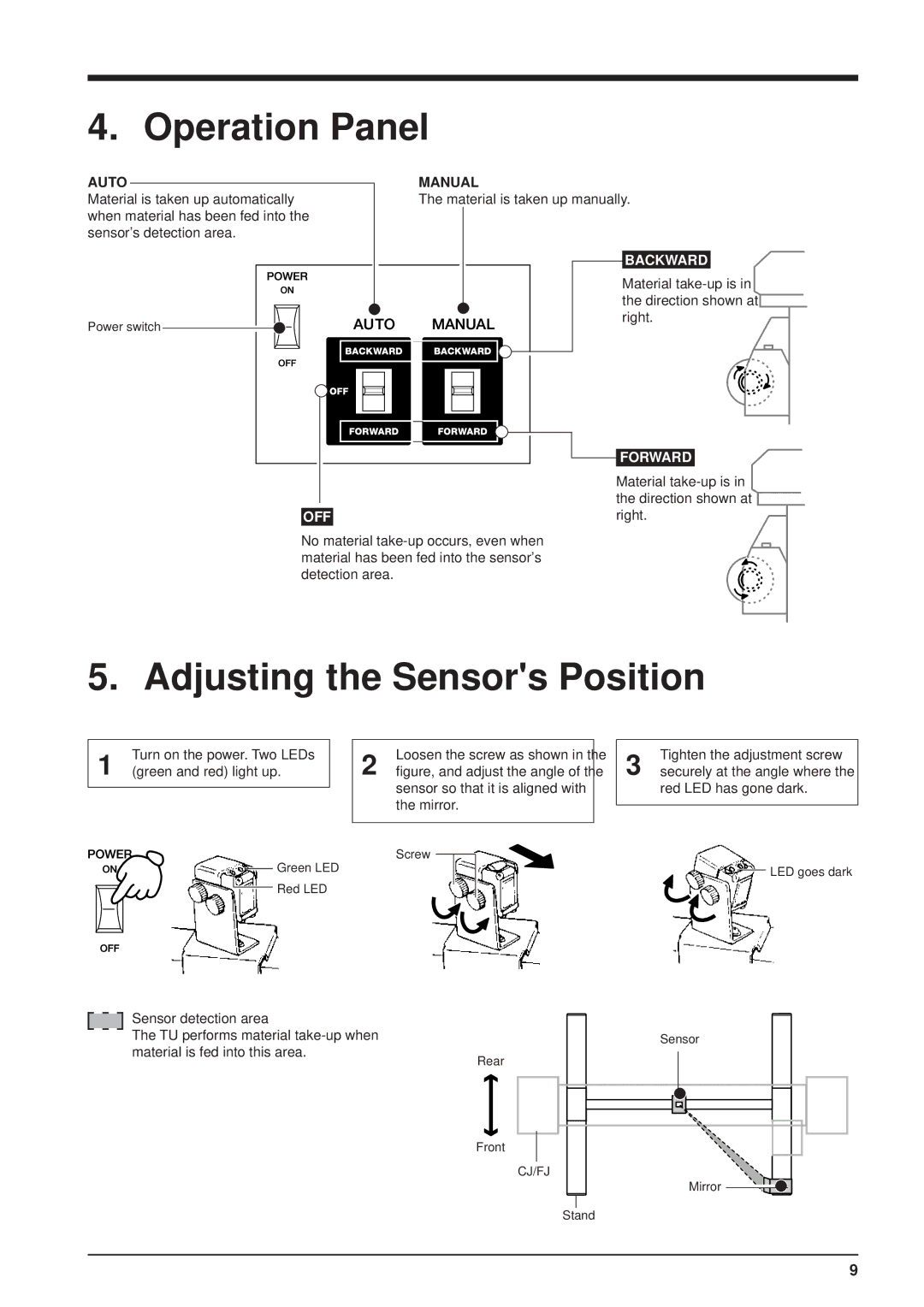
4. Operation Panel
AUTO |
|
|
|
|
|
|
| MANUAL | |||||||||
|
|
|
|
|
| ||||||||||||
Material is taken up automatically |
|
|
|
| The material is taken up manually. | ||||||||||||
when material has been fed into the |
|
|
|
|
|
|
|
|
|
|
|
| |||||
sensor's detection area. |
|
|
|
|
|
|
|
|
|
|
|
| |||||
|
|
|
|
|
|
|
|
|
|
|
|
|
|
|
|
|
|
|
|
|
|
|
|
|
|
|
|
|
|
|
|
|
| BACKWARD |
|
|
|
|
|
|
|
|
|
|
|
|
|
|
|
|
| Material | |
|
|
|
|
|
|
|
|
|
|
|
|
|
|
|
| the direction shown at | |
Power switch |
|
|
|
|
|
|
|
|
|
|
|
|
|
| right. | ||
|
|
|
| ||||||||||||||
|
|
|
|
|
|
|
|
|
|
|
|
|
|
| |||
|
|
|
|
|
|
|
|
|
|
|
|
|
|
| |||
|
|
|
|
|
|
|
|
|
|
|
|
|
|
|
|
|
|
|
|
|
|
|
|
|
|
|
|
|
|
|
|
|
|
|
|
|
|
|
|
|
|
|
|
|
|
|
|
|
|
|
|
|
|
|
|
|
|
|
|
|
|
|
|
|
|
|
|
|
|
|
|
|
|
|
|
|
|
|
|
|
|
|
|
|
|
|
|
|
|
|
|
|
|
|
|
|
|
|
|
|
|
|
|
|
|
|
|
|
|
|
|
|
|
|
|
|
|
|
|
|
|
|
|
|
|
|
|
|
|
|
|
|
|
|
|
|
|
|
|
|
|
|
|
|
|
|
|
|
|
|
|
|
|
|
|
|
|
|
|
|
|
|
|
|
|
|
|
|
|
|
|
|
|
|
|
|
|
|
|
|
|
|
|
|
|
|
|
|
|
|
|
|
|
|
|
|
|
|
|
|
|
|
|
|
|
|
|
|
|
|
|
|
|
|
|
|
|
|
|
|
| FORWARD |
|
|
|
|
|
|
|
|
|
|
|
|
|
|
|
|
|
|
| |
|
|
|
|
|
|
|
|
|
|
|
|
|
|
|
|
| Material | |
|
|
|
|
|
|
|
|
|
|
|
|
|
|
|
|
| the direction shown at | |
|
|
|
|
|
|
|
|
|
|
|
|
|
|
|
|
| ||
|
|
|
|
|
|
|
|
|
|
|
|
|
|
|
|
| right. | |
| OFF |
|
|
|
|
|
|
|
|
|
|
|
|
|
| |||
No material |
|
|
|
| ||||||||||||||
material has been fed into the sensor's |
|
|
|
| ||||||||||||||
detection area. |
|
|
|
| ||||||||||||||
5. Adjusting the Sensor's Position
Turn on the power. Two LEDs
1 (green and red) light up.
Loosen the screw as shown in the
2 figure, and adjust the angle of the sensor so that it is aligned with the mirror.
Tighten the adjustment screw
3 securely at the angle where the red LED has gone dark.
Screw
![]() Green LED
Green LED
![]() Red LED
Red LED
Sensor detection area
The TU performs material
![]() LED goes dark
LED goes dark
Sensor
Rear
Front
CJ/FJ
Mirror
Stand
9