Q-750I specifications
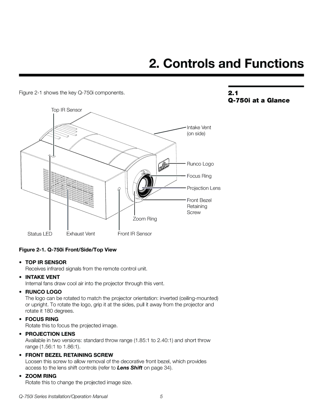
The Runco Q-750I is a state-of-the-art home theater projector that has earned a reputation for delivering exceptional image quality and advanced features. Designed to cater to the needs of cinephiles and home theater enthusiasts alike, the Q-750I incorporates a range of technologies that elevate the viewing experience to new heights.One of the standout characteristics of the Runco Q-750I is its use of cutting-edge DLP technology. The projector employs a BrilliantColor™ technology that enhances the color accuracy and brightness, delivering vivid and realistic images. With a native resolution of 1080p, it ensures that even the smallest details in high-definition content are rendered crisply and clearly.
In addition to its impressive resolution, the Q-750I also features an advanced optical system. The projector's lens system, which includes multiple lens elements, ensures minimal distortion and superior image sharpness across the entire screen. This attention to detail means that viewers can enjoy an immersive cinematic experience without compromising on image quality.
The Q-750I also stands out with its extensive installation flexibility. With a motorized lens shift feature, users can easily adjust the projector's position to fit various screen sizes and setups. This aspect, combined with a robust zoom capability, allows for seamless integration into any home theater design.
Another significant feature of the Runco Q-750I is its support for 3D content. With the increasing popularity of 3D films and gaming, the Q-750I can project stunning three-dimensional visuals, providing an engaging experience that makes viewers feel part of the action. It is compatible with the latest 3D formats, ensuring that users can enjoy their favorite content without any compromise.
Moreover, the projector is equipped with Runco's proprietary Vivix™ video processing technology. This advanced processing system enhances the quality of both standard and high-definition content, optimizing color, contrast, and motion handling. The result is a smoother and more lifelike viewing experience, particularly in dynamic scenes.
On the connectivity front, the Q-750I is well-equipped with multiple input options, including HDMI, Component, and RS-232 for integration with control systems. This ensures compatibility with a wide range of devices, making it a versatile choice for any home theater setup.
In summary, the Runco Q-750I is a feature-packed projector that combines high-end technologies with user-friendly design. Its impressive image quality, installation versatility, and support for 3D content make it an ideal choice for anyone looking to create a truly immersive home theater experience. As technology continues to evolve, the Q-750I stands out as a premium option for discerning viewers who demand the best in home entertainment.

