SC-1
Page
TWO Year Limited Warranty
For Projectors, Video Processors and Controllers
Effective Warranty Date
Runco INTERNATIONAL, INC
Safety Precautions
Table of Contents
Installing the Extractor Fan and Exhaust Duct
Maintenance and Troubleshooting
Operation
103
Specifications
Serial Communications
List of Figures
107
About This Manual
Significance. They also provide supplemental information
Using This Manual
Certain features
Degrade performance or cause a malfunction
Description, Features and Benefits
Optional Accessories
Controls and Functions
SC-1 at a Glance
Ballast Control Connector 9-pin, D-sub male
SC-1 requires a dedicated, 220-VAC/30A circuit. Connect
SC-1 Input Panel
2shows the SC-1 rear input panel
Input 2 DVI
Input 3 Video / Input 4 S-Video
SC-1 Control Panel
SC-1 Control Panel
Menu
Input 1 BNC
Menu Navigation Buttons
SC-1 has its own internal menu system, separate from that
DHD Controller Front Panel
DHD Controller Front Panel
DHD Controller Rear Panel
DHD Controller Rear Panel Outputs 1. Analog Outputs Rgbhv
Inputs
DHD Controller Remote Control
DHD Controller Remote Control
For more information about aspect ratios, refer to Table
On / OFF
Cursor Buttons
Video
ANA Anamorphic
Memory Preset Buttons ISF NT Night
Aspect Ratio Selection Buttons
4X3 Standard 43
Installation
Remote Control
Installation specialist
Quick Setup
Step Procedure For Details, Refer to
Rear Screen, Floor Mount Installation
Installation Considerations
Installation Type
Ambient Light
Screen Lens Throw Ratio = Approximate Throw Distance
SC-1 Lens Options and Throw Ratios
Minimum Maximum
Position
Vertical and Horizontal
Lens Shift
20% Offset
Installing the Primary Lens
Installing the Projection Lens, Lamp and Cooling
Moving the SC-1 Other Considerations
Installing the Primary Lens
Remove Lamp/Air Filter Cover Lamp Cooling Compartment Door
Lamp Cradle Adjustment
Measured linear ft/min x 0.34 = CFM
Installing the Extractor
Do not exceed 6-ft. duct length without adding additional
Installing the Optional CineWide Lens Mount
Raise the Feet
To Lens Motor
Install Anamorphic Lens Motor
Attach Extension Bracket
Are both fully assembled
Do not attempt to invert or ceiling-mount the SC-1
Adjusting the Feet
Mounting the SC-1
Tilting the Projector
Connections to the SC-1 and DHD Controller
Connecting the DHD
Controller to the SC-1
13. Connecting the SC-1 to the DHD Controller
DHD Controller
Connecting Source
Digital DTV RGB or Component Video Connections See Figure
15. Digital DTV RGB or Component Video Connections
Analog Computer RGB Connections See Figure
16. Analog RGB Connections
Composite/S-Video/Component Video Connections See Figure
17. Composite, S-Video and Component Video Connections
Connection
Connecting 12-Volt
RS-232 Controller
Trigger Outputs to
Continue with the next step, Connecting to AC Power
20. External Power Supply/Ballast Connection
From Ballast
22. AC/Lamp Control Input Panel
Input voltage to the AutoScope lens motor must be between
Turning on the Power
Defining the Installed Lamp Size
SC-1 DVI
24. Using LampLOC to Align the Lamp
Maximizing Light Output
You must enter a passcode to access the Service menu
Zoom
Focus
Horizontal and Vertical
It is extremely important that the primary lens is properly
Installing and Adjusting the CineWide Anamorphic Lens
Assembly to Lens Motor
Carriage Plate
27. Attaching the Anamorphic Lens to the Lens Ring
Horizontal Position X Adjustment
Configure Lens Motor
Adjust the Anamorphic
Trigger
Too Low Correct position Too High
Wrong Position Correct Position
Geometry
Calibrating Projector Inputs
Main
TheaterMaster Remote
Control Functions
Menus
Are disabled
Navigating the Projector
Enter or
30. Copying a Channel
You cannot use Auto Setup with a locked channel. Copy
Size and Position Menu
Native aspect ratio is with the primary lens only. With
Adjust Pixel Tracking before Pixel Phase
Image Settings Menu
Values shown represent where the approximate center
Needed see below
Non-video images
Uncheck this item before exiting this menu
Lamp
Working With the Lamp
Originally expected may no longer be possible
Intensity value is not the actual lumen output, but rather a
More easily maintained as the lamp ages
Using the On-Screen Menus
Operation
Input Source
ISF Presets
Service
Aspect Ratio
Aspect Ratio
Main Menu
Input Source
HD Pass Thru 1 HD Pass Thru
Aspect Ratio Settings
Remote Aspect Ratio Control Description Key
Picture
Picture Brightness Contrast Color Tint Sharpness
Typical Pluge Pattern for Adjusting Brightness
Gray Yellow Cyan Green Magenta Red Blue
Gray Yellow Cyan Green Magenta Red Blue
Input Position
Resolution
Input Position Left/Right Up/Down Width Height Overscan
Information
ISF Presets
ISF Presets ISF Night ISF Day Custom Save Factory Default
Serial Number Hardware Firmware 0002.003A Date Mar 15
ISF Day Display Color Refer to ISF Night Display Color
You must enter a passcode to access the Calibration menu
Calibration
Operation
Service
Button takes you from top to bottom in the left column, then
Tip
HD/RGB 1 and HD/RGB 2 Color Space Select Auto, RGB or YUV
ADC Bandwidth Auto YPbPr Input Resolution
Auto
Operation
AC/Power Precautions
Safety Guidelines
Never look directly into the projector lens or at the lamp.
Maintaining Proper
Cooling
Maintenance and Cleaning
Electrical Optical Required Materials and Supplies
Cleaning Other
Cleaning the Lens Removing Dust
Cleaning the Reflector Removing Dust
Removing Fingerprints, Smudges, Oil and Other Substances
Lamp and Filter Replacement
Lamp Replacement
Disconnecting the Old Lamp
Installing a New Lamp
Record the New Lamp Serial Number
Recording the Serial Number of a New Lamp
Filter Replacement
Lens Replacement
Lamp is accurate
Troubleshooting Tips
Symptom Possible Causes Solution
Configure Lens Motor
Code Description General
Lamp Failures
Tipm Image Processor
Code Description Power and Cooling
Built-In Keypad
Code Description Panel Driver and Formatter
RS-232 Connection and Port Configuration
Serial Command Syntax
Value Description Min/max Stored? Power On/Off Commands
Command
Input Selection Commands
Picture Adjust Commands
Input Position Commands
Value Description Min/max Stored? Image Preset Commands
Output Shift Commands
Runco SC-1 Owner’s Operating Manual 101
102 Runco SC-1 Owner’s Operating Manual
SC-1 Specifications
Power Requirements
Home Theater Calibration Specifications
Industry-Standard Specifications
Dimensions
DHD Controller Specifications
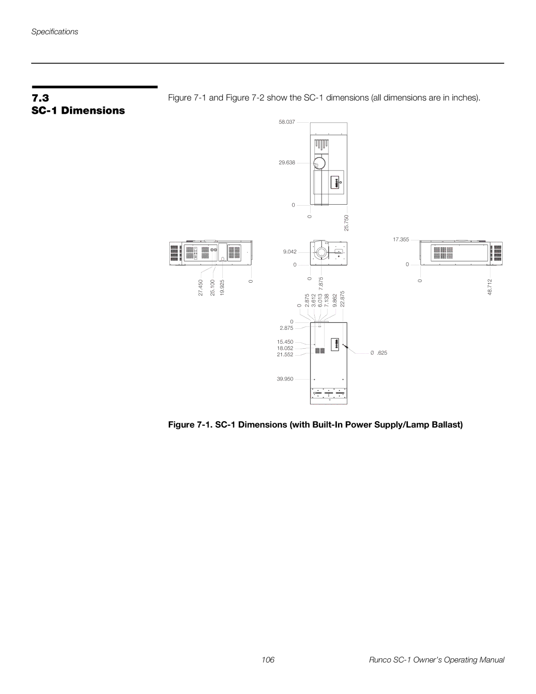
SC-1 Dimensions
SC-1 Dimensions with Built-In Power Supply/Lamp Ballast
SC-1 Dimensions without Built-In Power Supply/Lamp Ballast
108 Runco SC-1 Owner’s Operating Manual
Page
Runco CL-810 Owner’s Operating Manual