ADJUSTMENTS
Bevel Adjustment
See Figures 11 and 12.
Your drill press is equipped with a tilting table that allows you to drill angled holes. The table can be tilted left or right, from
To tilt the table, loosen the large hex bolt located underneath the table. Use the bevel scale to tilt table to the desired angle, then tighten hex bolt.
TABLE LOCK | HEX BOLT |
| |
HANDLE | Fig. 11 |
BEVEL SCALE
Fig. 12
Table Rotation
See Figure 11.
When drilling large objects it may be necessary to swing the table out of the way. Simply loosen the table lock lever, rotate table, and retighten table lock lever.
Note: When using the base as a work surface, the workpiece must be clamped securely to the base.
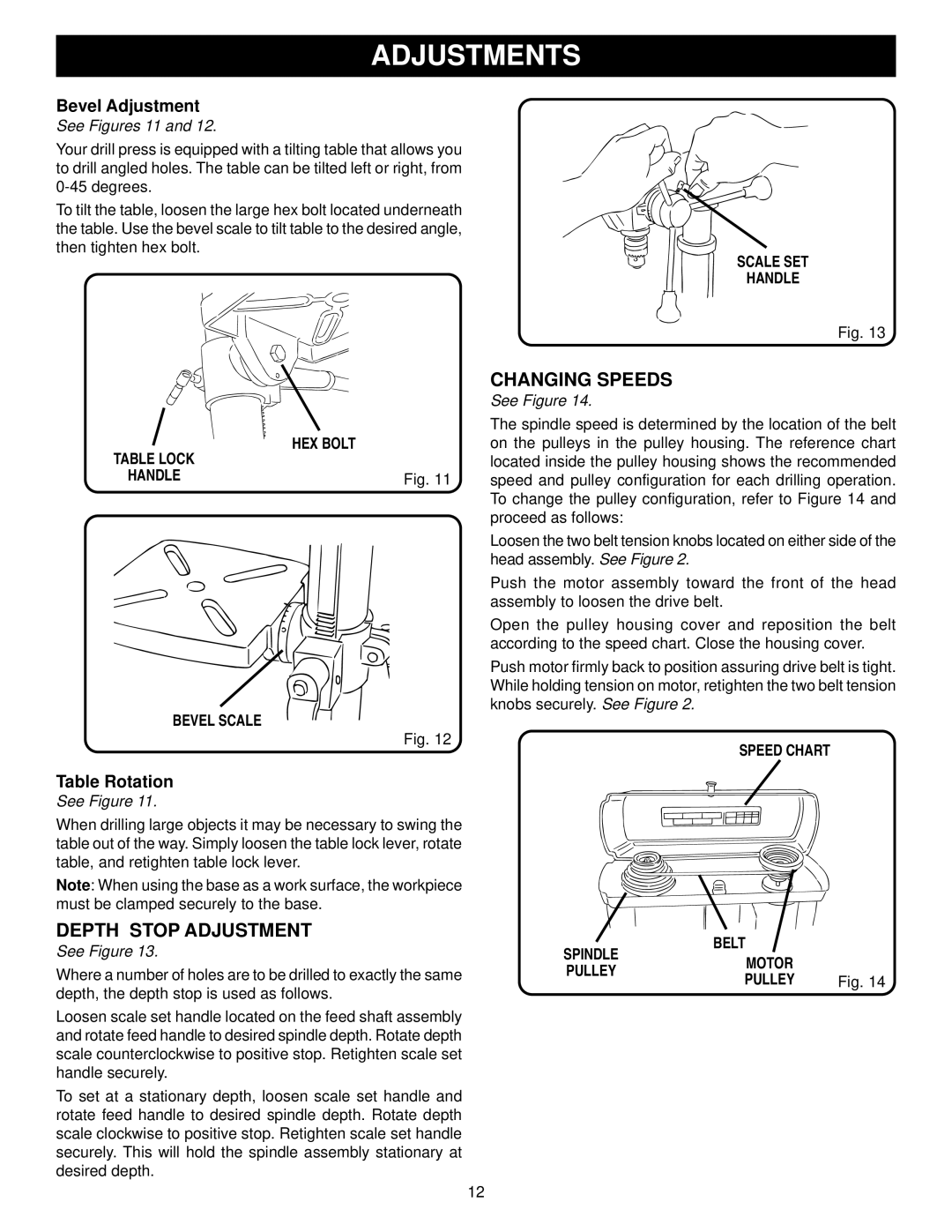
DEPTH STOP ADJUSTMENT
See Figure 13.
Where a number of holes are to be drilled to exactly the same depth, the depth stop is used as follows.
Loosen scale set handle located on the feed shaft assembly and rotate feed handle to desired spindle depth. Rotate depth scale counterclockwise to positive stop. Retighten scale set handle securely.
To set at a stationary depth, loosen scale set handle and rotate feed handle to desired spindle depth. Rotate depth scale clockwise to positive stop. Retighten scale set handle securely. This will hold the spindle assembly stationary at desired depth.
SCALE SET
HANDLE
Fig. 13
CHANGING SPEEDS
See Figure 14.
The spindle speed is determined by the location of the belt on the pulleys in the pulley housing. The reference chart located inside the pulley housing shows the recommended speed and pulley configuration for each drilling operation. To change the pulley configuration, refer to Figure 14 and proceed as follows:
Loosen the two belt tension knobs located on either side of the head assembly. See Figure 2.
Push the motor assembly toward the front of the head assembly to loosen the drive belt.
Open the pulley housing cover and reposition the belt according to the speed chart. Close the housing cover.
Push motor firmly back to position assuring drive belt is tight. While holding tension on motor, retighten the two belt tension knobs securely. See Figure 2.
SPEED CHART
SPINDLE | BELT |
| |
MOTOR |
| ||
PULLEY |
| ||
PULLEY | Fig. 14 | ||
|
12