Connecting the assembly cable
 Cable specification
Model | Power cable | Interconnection cable | Type GL |
12 | 3G x 1.0 mm², | 4G x 1.0 mm², | 20 A |
18 | 3G x 2.5 mm², | 4G x 1.5 mm², | 25 A |
24 | 3G x 2.5 mm², | 4G x 2.5 mm², | 25 A |
• Connect the power cable to the auxiliary circuit breaker. If every pole fails to connect to the power supply, it must be incorporated in a wire with a contact opening of ≥ 3 mm
• Use shield cable (Category 5; less than 50pF/m) for noisy environmental site.
 Connecting the cable
Electrical work
(1)For electrical and earth works, comply with the‘technical standards of electrical installations’and the the‘wiring regulations’of the Local wiring regulations.
(2)Tighten the terminal block screw to 1.2~1.8 N•m (12~18 kgf•cm).
(3)Precautions when connecting terminal blocks of the indoor unit
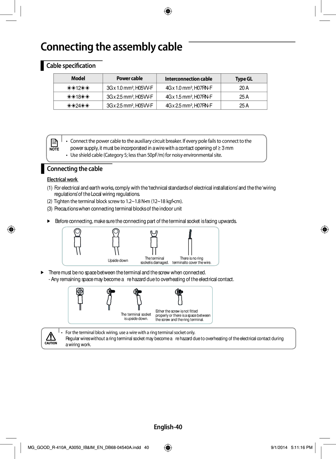
Before connecting, make sure the connecting part of the terminal socket is facing upwards.
Upside down | The terminal | There is no ring | |
socketis damaged. | terminalto cover the wire. | ||
|
There must be no space between the terminal and the screw when connected.
- Any remaining space may become a fire hazard due to overheating of the electrical contact.
|
| Either the screw is not fitted | |
The terminal socket | |||
properly or there is a space between | |||
is upside down. | the screw and the ring terminal. | ||
• For the terminal block wiring, use a wire with a ring terminal socket only.
Regular wires without a ring terminal socket may become a fire hazard due to overheating of the electrical contact during a wiring work.
English-40
9/1/2014 5:11:16 PM
