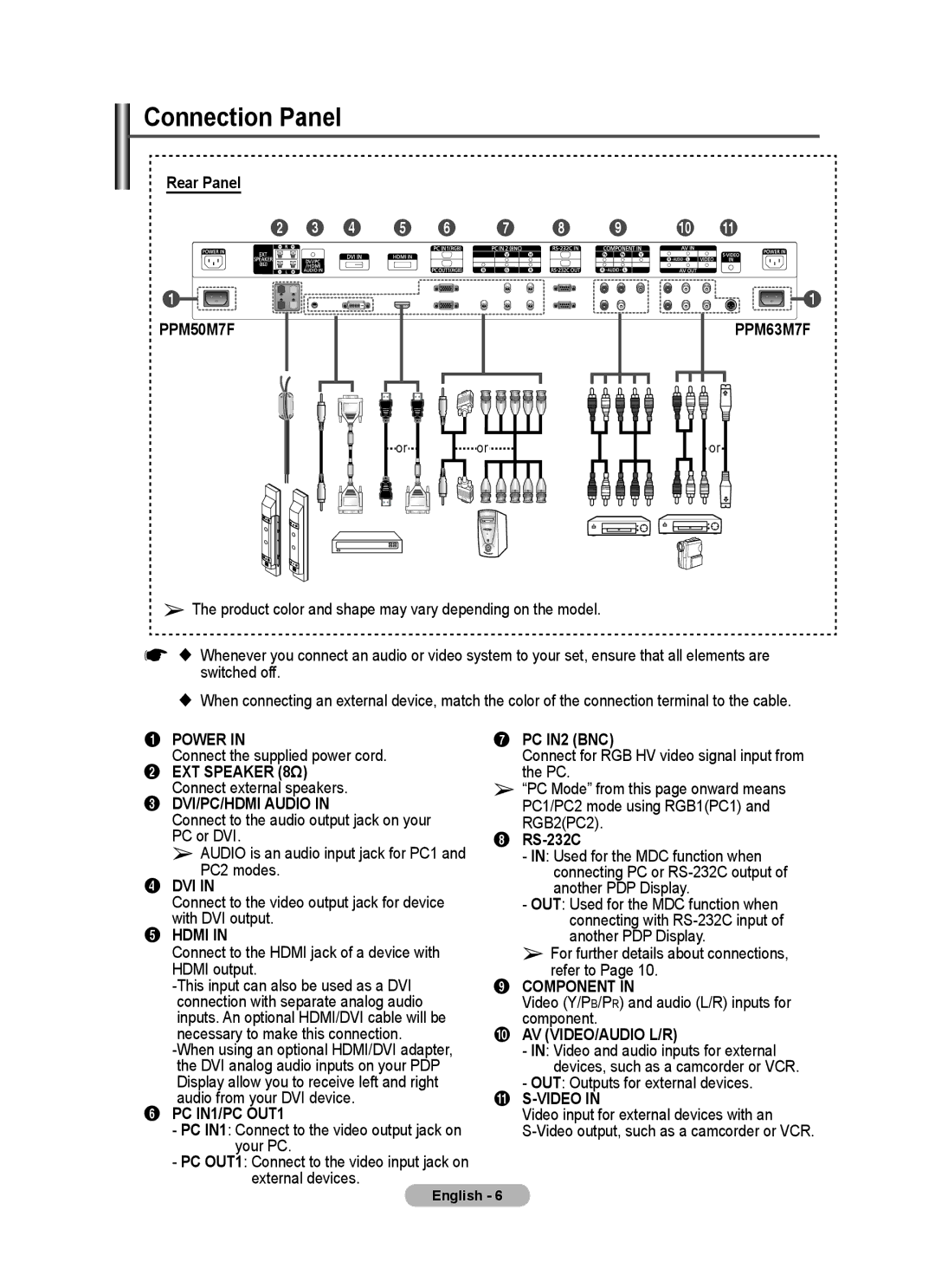
Connection Panel
Rear Panel
2 3 4 5 6
1![]()
![]()
PPM50M7F
7 8 9 0 !
![]() 1
1
PPM63M7F
or
or
or
➢The product color and shape may vary depending on the model.
☛ Whenever you connect an audio or video system to your set, ensure that all elements are switched off.
When connecting an external device, match the color of the connection terminal to the cable.
1 POWER IN
Connect the supplied power cord.
2 EXT SPEAKER (8Ω) Connect external speakers.
3 DVI/PC/HDMI AUDIO IN
Connect to the audio output jack on your PC or DVI.
➢ AUDIO is an audio input jack for PC1 and PC2 modes.
4 DVI IN
Connect to the video output jack for device with DVI output.
5HDMI IN
Connect to the HDMI jack of a device with
HDMI output.
6 PC IN1/PC OUT1
- PC IN1: Connect to the video output jack on your PC.
- PC OUT1: Connect to the video input jack on external devices.
7 PC IN2 (BNC)
Connect for RGB HV video signal input from the PC.
➢ “PC Mode” from this page onward means PC1/PC2 mode using RGB1(PC1) and RGB2(PC2).
8 RS-232C
- IN: Used for the MDC function when connecting PC or
- OUT: Used for the MDC function when connecting with
➢ For further details about connections, refer to Page 10.
9 COMPONENT IN
Video (Y/PB/PR) and audio (L/R) inputs for component.
0 AV (VIDEO/AUDIO L/R)
- IN: Video and audio inputs for external devices, such as a camcorder or VCR.
- OUT: Outputs for external devices.
! S-VIDEO IN
Video input for external devices with an
English - 6