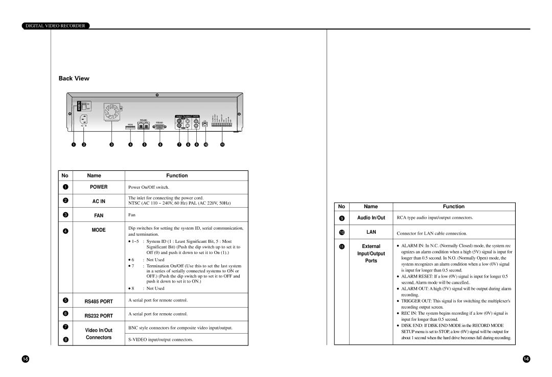
SCR-3000P specifications
The Samsung SCR-3000P is an innovative mobile device that combines cutting-edge technology with user-centric design, making it a standout option in today's competitive market. This device exemplifies Samsung's commitment to delivering advanced features in a sleek and sophisticated form.At the heart of the SCR-3000P lies a robust processor that ensures smooth performance across all applications. Whether users are multitasking between various apps or streaming high-definition content, the device handles everything with ease. The impressive RAM capacity further enhances this multitasking capability, allowing for seamless transitions and efficient management of resources.
One of the key highlights of the SCR-3000P is its stunning display. Equipped with a high-resolution screen, the device offers vibrant colors and sharp contrast, making it ideal for both media consumption and productivity tasks. The display also features cutting-edge technology that ensures optimal visibility in various lighting conditions, whether indoors or outside in direct sunlight.
In terms of photography, the SCR-3000P boasts a powerful camera system that includes multiple lenses designed for versatility. Users can capture stunning images with high detail and clarity, aided by advanced features such as optical image stabilization and low-light performance enhancements. The front-facing camera is equally impressive, catering to selfie enthusiasts and video callers alike.
Battery life is another significant aspect of the SCR-3000P. The device is equipped with a high-capacity battery that supports fast charging technology, ensuring that users can spend more time enjoying their device and less time tethered to a power outlet. Additionally, power-saving modes help maximize usage time, making it a reliable choice for those on the go.
Security features are paramount in today's digital landscape, and the SCR-3000P does not disappoint. It includes biometric authentication methods such as fingerprint recognition and facial recognition, providing users with peace of mind regarding data protection and privacy.
Connectivity options are robust, with support for the latest wireless technologies, including 5G, Wi-Fi 6, and Bluetooth 5.0. This ensures that users can enjoy fast internet speeds and seamless connections to other devices, enhancing the overall user experience.
In conclusion, the Samsung SCR-3000P is a remarkable device that delivers a blend of performance, design, and functionality. With its array of features tailored to meet the needs of modern users, it stands out as a compelling choice for anyone in search of a high-quality mobile device.

