Part Names and Functions
Camera ID |
| ||||||||
250 | ON | ON | ON | ON | ON | OFF | ON | OFF |
|
251 | ON | ON | ON | ON | ON | OFF | ON | ON |
|
252 | ON | ON | ON | ON | ON | ON | OFF | OFF |
|
253 | ON | ON | ON | ON | ON | ON | OFF | ON |
|
254 | ON | ON | ON | ON | ON | ON | ON | OFF |
|
255 | ON | ON | ON | ON | ON | ON | ON | ON |
|
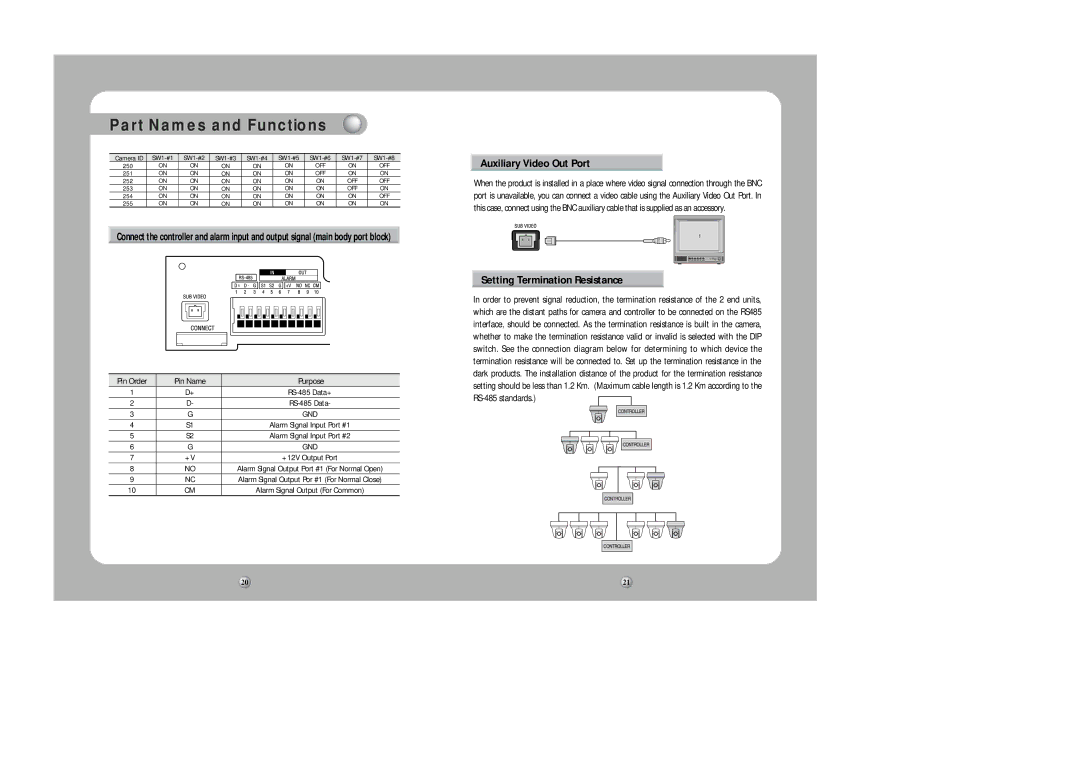
Connect the controller and alarm input and output signal (main body port block)
Pin Order | Pin Name | Purpose |
1 | D+ | |
2 | D- | |
3 | G | GND |
4 | S1 | Alarm Signal Input Port #1 |
5 | S2 | Alarm Signal Input Port #2 |
6 | G | GND |
7 | +V | +12V Output Port |
8 | NO | Alarm Signal Output Port #1 (For Normal Open) |
9 | NC | Alarm Signal Output Por #1 (For Normal Close) |
10 | CM | Alarm Signal Output (For Common) |
Auxiliary Video Out Port
When the product is installed in a place where video signal connection through the BNC port is unavailable, you can connect a video cable using the Auxiliary Video Out Port. In this case, connect using the BNC auxiliary cable that is supplied as an accessory.
Setting Termination Resistance
In order to prevent signal reduction, the termination resistance of the 2 end units, which are the distant paths for camera and controller to be connected on the RS485 interface, should be connected. As the termination resistance is built in the camera, whether to make the termination resistance valid or invalid is selected with the DIP switch. See the connection diagram below for determining to which device the termination resistance will be connected to. Set up the termination resistance in the dark products. The installation distance of the product for the termination resistance setting should be less than 1.2 Km. (Maximum cable length is 1.2 Km according to the ![]()
20 | 21 |