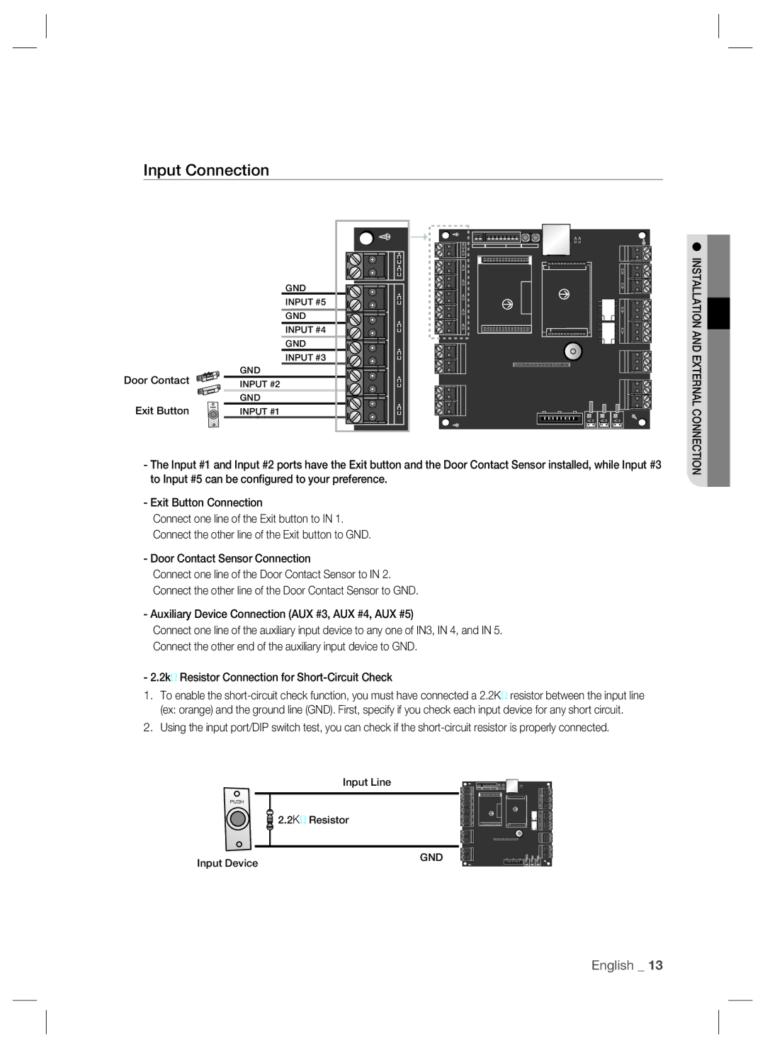
Input Connection
Door Contact
Exit Button
PUSH
GND
INPUT #5
GND
INPUT #4
GND
INPUT #3
GND
INPUT #2
GND
INPUT #1
INSTALLATION AND EXTERNAL CONNECTION
-The Input #1 and Input #2 ports have the Exit button and the Door Contact Sensor installed, while Input #3 to Input #5 can be configured to your preference.
-Exit Button Connection
Connect one line of the Exit button to IN 1.
Connect the other line of the Exit button to GND.
- Door Contact Sensor Connection
Connect one line of the Door Contact Sensor to IN 2.
Connect the other line of the Door Contact Sensor to GND.
- Auxiliary Device Connection (AUX #3, AUX #4, AUX #5)
Connect one line of the auxiliary input device to any one of IN3, IN 4, and IN 5.
Connect the other end of the auxiliary input device to GND.
- 2.2kΩ Resistor Connection for
1.To enable the
2.Using the input port/DIP switch test, you can check if the
Input Line
PUSH
![]() 2.2KΩ Resistor
2.2KΩ Resistor
Input Device
GND
English _ 13