installation and external connection
POWER, READER, AND I/O CONNECTION
Power Connection
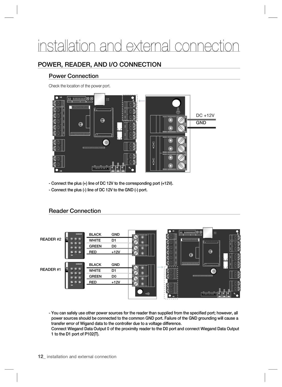
Check the location of the power port.
DC +12V
GND
-Connect the plus (+) line of DC 12V to the corresponding port (+12V).
-Connect the plus
Reader Connection
READER #2
READER #1
X Y Z
[\ ] ^ _ `
lzj W lu{
i
X Y Z
[\ ] ^ _ `
lzj W lu{
i
BLACK | GND |
|
|
|
|
|
|
|
| ||
WHITE | D1 |
|
|
|
|
|
|
| |||
|
|
| |||
GREEN | D0 |
|
|
|
|
|
|
| |||
|
|
| |||
RED | +12V |
|
|
|
|
|
|
|
| ||
|
|
| |||
BLACK | GND |
|
|
|
|
|
|
|
| ||
|
|
|
|
|
|
WHITE | D1 |
|
|
|
|
|
|
| |||
|
|
| |||
GREEN | D0 |
|
|
|
|
|
|
|
| ||
RED | +12V |
|
|
|
|
|
|
|
| ||
|
|
| |||
|
|
|
|
|
|
|
|
|
|
|
|
|
|
|
|
|
|
-You can safely use other power sources for the reader than supplied from the specified port; however, all power sources should be connected to the common GND port. Failure of the GND grounding will cause a transfer error of Wigand data to the controller due to a voltage difference.
Connect Wiegand Data Output 0 of the proximity reader to the D0 port and connect Wiegand Data Output 1 to the D1 port of P102(T).
12_ installation and external connection
