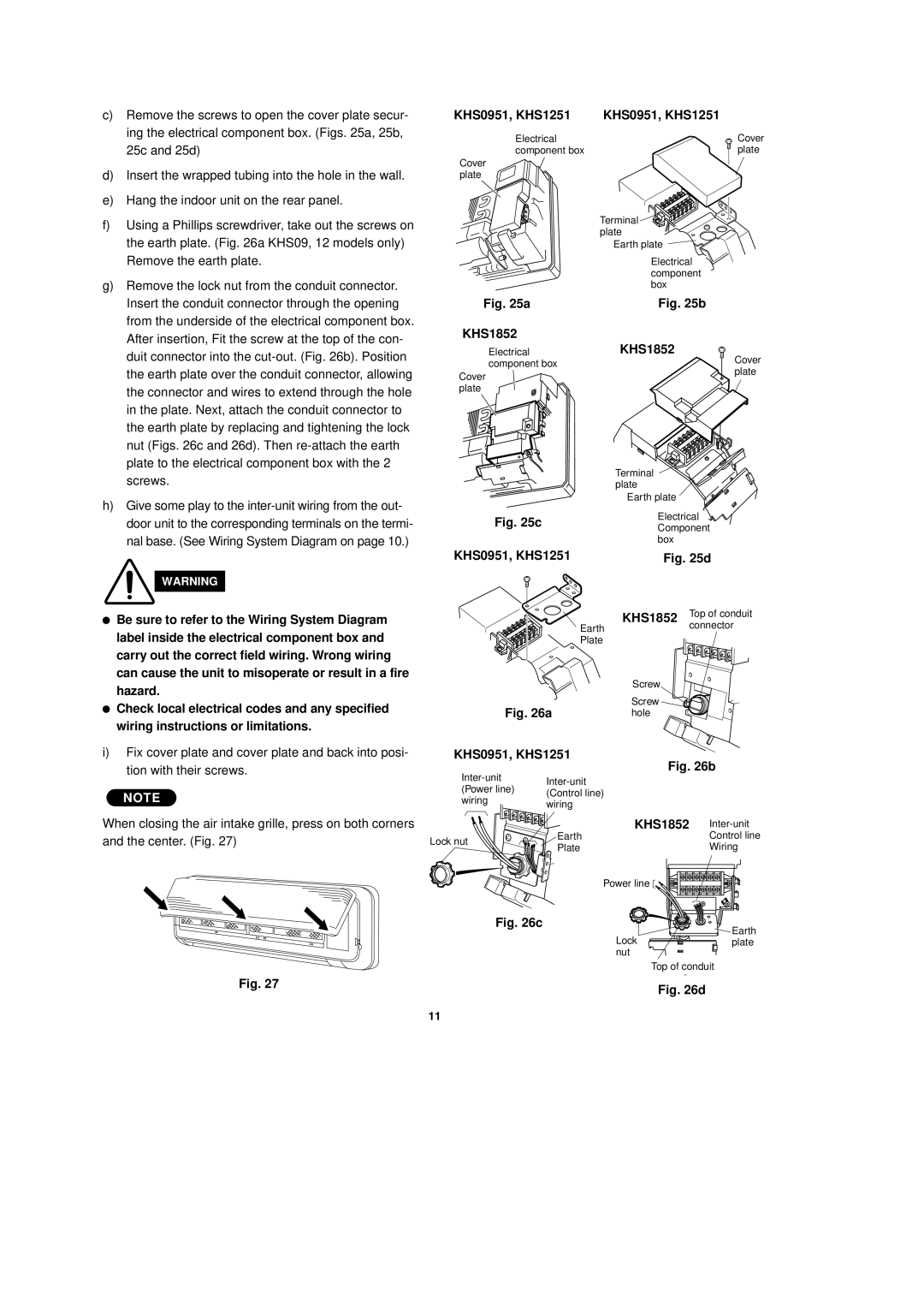
c)Remove the screws to open the cover plate secur- ing the electrical component box. (Figs. 25a, 25b, 25c and 25d)
d)Insert the wrapped tubing into the hole in the wall.
e)Hang the indoor unit on the rear panel.
f)Using a Phillips screwdriver, take out the screws on the earth plate. (Fig. 26a KHS09, 12 models only) Remove the earth plate.
g)Remove the lock nut from the conduit connector. Insert the conduit connector through the opening from the underside of the electrical component box. After insertion, Fit the screw at the top of the con- duit connector into the
h)Give some play to the
WARNING
●Be sure to refer to the Wiring System Diagram label inside the electrical component box and carry out the correct field wiring. Wrong wiring can cause the unit to misoperate or result in a fire hazard.
●Check local electrical codes and any specified wiring instructions or limitations.
i)Fix cover plate and cover plate and back into posi- tion with their screws.
NOTE
When closing the air intake grille, press on both corners and the center. (Fig. 27)
Fig. 27
KHS0951, KHS1251 | KHS0951, KHS1251 | |
Electrical | Cover | |
component box | plate | |
Cover |
| |
plate |
| |
| Terminal | |
| plate | |
| Earth plate | |
| Electrical | |
| component | |
| box | |
Fig. 25a | Fig. 25b | |
KHS1852 |
| |
Electrical | KHS1852 | |
component box | Cover | |
plate | ||
Cover | ||
| ||
plate |
|
|
| Terminal |
|
|
| plate |
|
|
| Earth plate |
|
Fig. 25c |
| Electrical | |
| Component | ||
|
| ||
|
| box |
|
KHS0951, KHS1251 | Fig. 25d | ||
|
| KHS1852 | Top of conduit |
| Earth |
| connector |
|
|
| |
| Plate |
|
|
|
| Screw |
|
Fig. 26a | Screw |
| |
hole |
| ||
KHS0951, KHS1251 | Fig. 26b | ||
| |||
|
| ||
(Power line) |
|
| |
(Control line) |
|
| |
wiring |
|
| |
wiring |
|
| |
|
|
| |
|
| KHS1852 | |
Lock nut | Earth |
| Control line |
Plate |
| Wiring | |
|
| ||
| Power line |
| |
Fig. 26c |
|
| Earth |
|
| Lock | |
|
| plate | |
|
| nut |
|
Top of conduit
t
Fig. 26d
11