LOCATIONS OF CONTROLS AND INDICATORS
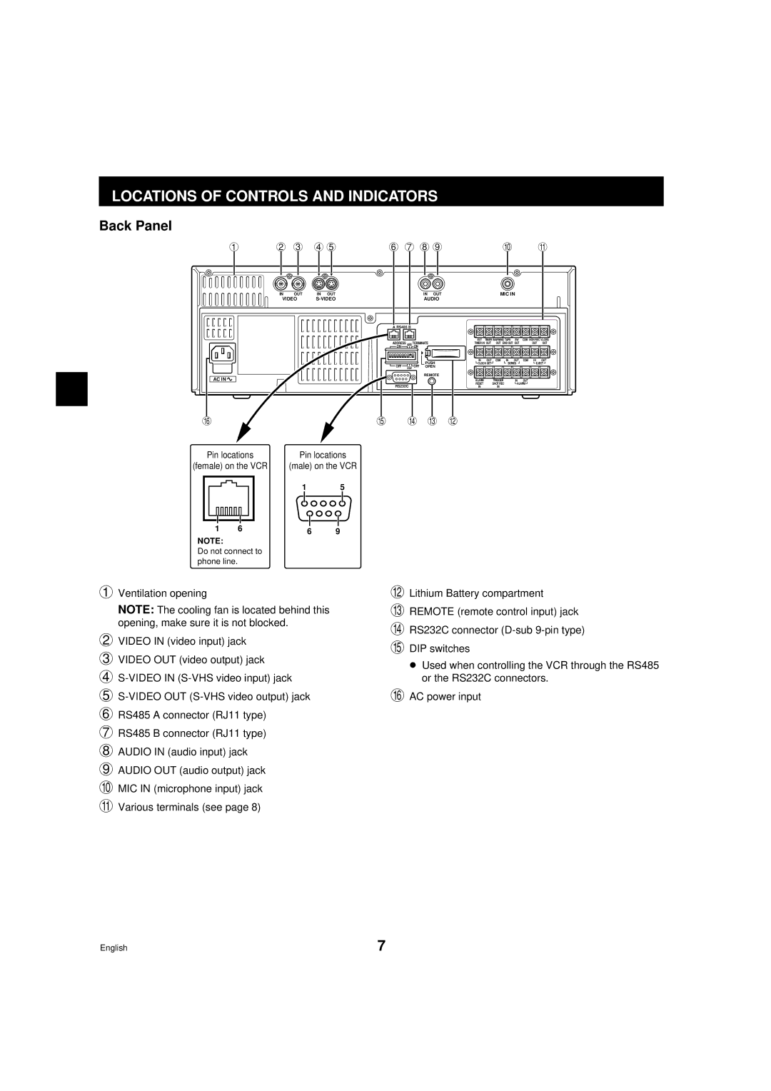
Back Panel
1 | 2 3 45 | 6 7 89 | F G |
IN | OUT | IN OUT | IN OUT |
VIDEO | AUDIO | ||
|
| A RS485 B | |
|
| ADDRESS | 485 TERMINATE |
|
| ON | ON |
|
|
| PUSH |
|
| OFF | 232 OFF OPEN |
AC IN |
|
| REMOTE |
|
|
| |
|
| RS232C | |
L |
| K | J I H |
Pin locations | Pin locations |
| |
(female) on the VCR | (male) on the VCR |
| |
| 1 | 5 |
|
MIC IN
EXT | TIMER WARNING TAPE | SW | COM NON REC V.LOSS | ||||
TIMER IN OUT | OUT | END OUT OUT |
| OUT | OUT | ||
IN | OUT | COM | IN | OUT | COM | IN | OUT |
CLOCK SET |
| SERIES |
| EJECT | |||
ALARM |
| TRIGGER | IN | OUT |
|
| |
RESET |
| SHOT REC | ALARM |
|
| ||
IN |
| IN |
|
|
|
|
|
|
|
|
|
|
|
|
|
1 | 6 | 6 | 9 | ||||
|
|
|
| ||||
NOTE:
Do not connect to phone line.
1 Ventilation opening
NOTE: The cooling fan is located behind this opening, make sure it is not blocked.
2 VIDEO IN (video input) jack
3 VIDEO OUT (video output) jack
4
5
7 RS485 B connector (RJ11 type)
8 AUDIO IN (audio input) jack
9 AUDIO OUT (audio output) jack F MIC IN (microphone input) jack G Various terminals (see page 8)
H I J K
L
Lithium Battery compartment
REMOTE (remote control input) jack
RS232C connector
DIP switches
œUsed when controlling the VCR through the RS485 or the RS232C connectors.
AC power input
English | 7 |
