SETUP FOR RS-232C OR RS-485 USE
Setup for RS-232C or RS-485 Use
1Press the MENU button to display the (MAIN MENU 1) menu.
2Press the SHIFT ] (or \) button until the (MAIN MENU 2) menu is displayed.
3Press the SHIFT ] (or \) button to select the “1.
øThe
øThe menu name will depend on the DIP switch 9 setting. When down
øThe STATUS INFO and ALARM INFO lines are only displayed when DIP switch 9 is set to 485.
4Press the DATA l (or j) button to set the desired transfer speed.

 19200
19200
 2400
2400
 4800
4800
 9600
9600

5Press the SHIFT ] button, until the “STATUS INFO” setting is flashing.
6Press the DATA l (or j) button to set the desired setting.
Y. . . . . . . . . The VCR status information (state information and warning state) and mode changes are output at the
N. . . . . . . . . The VCR status information (state information and warning state) and mode changes are not output at the
7Press the SHIFT ] button, until the “ALARM INFO” setting is flashing.
8Press the DATA l (or j) button to set the desired setting.
Y. . . . . . . . . . The VCR alarm information (alarm recording start and stop) and video loss information are output at the
N. . . . . . . . . The VCR alarm information (alarm recording start and stop) and video loss information are not output at the
9Press the MENU EXIT button to save the setting.
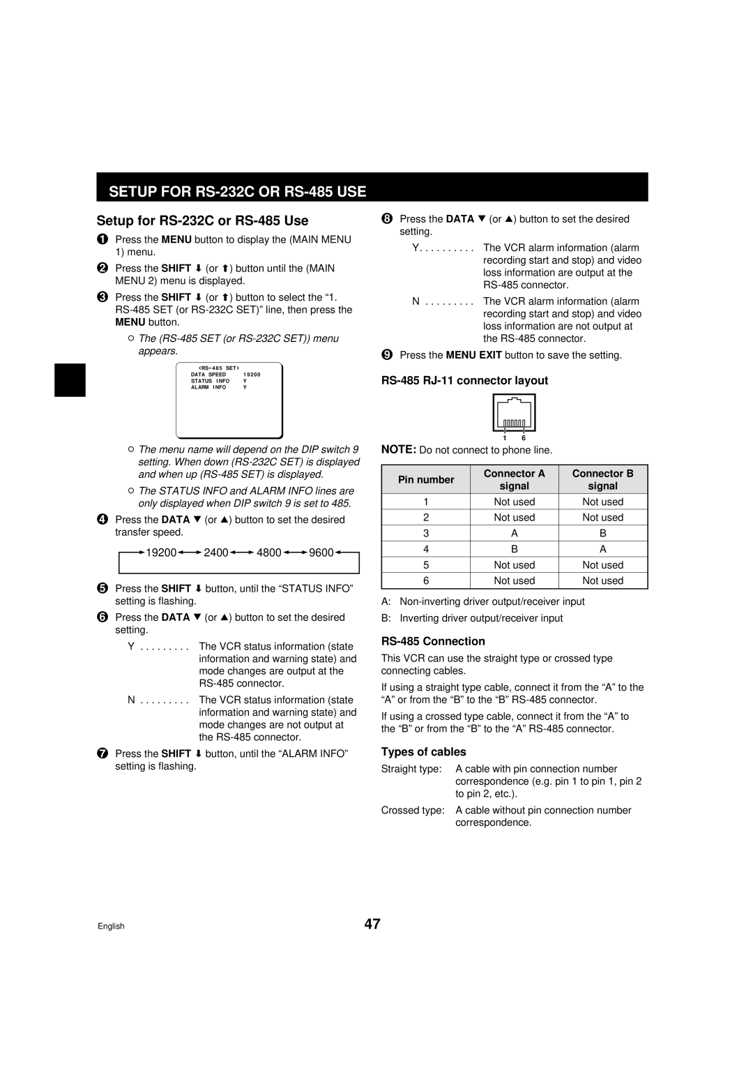
RS-485 RJ-11 connector layout
| 1 | 6 |
| |
NOTE: Do not connect to phone line. |
| |||
|
|
| ||
Pin number | Connector A | Connector B | ||
signal | signal | |||
| ||||
1 | Not used | Not used | ||
|
|
| ||
2 | Not used | Not used | ||
|
|
|
| |
3 |
| A | B | |
|
|
|
| |
4 |
| B | A | |
|
|
| ||
5 | Not used | Not used | ||
|
|
| ||
6 | Not used | Not used | ||
|
|
|
| |
A:
B:Inverting driver output/receiver input
RS-485 Connection
This VCR can use the straight type or crossed type connecting cables.
If using a straight type cable, connect it from the “A” to the “A” or from the “B” to the “B”
If using a crossed type cable, connect it from the “A” to the “B” or from the “B” to the “A”
Types of cables
Straight type: A cable with pin connection number correspondence (e.g. pin 1 to pin 1, pin 2 to pin 2, etc.).
Crossed type: A cable without pin connection number correspondence.
English | 47 |