SERIES RECORDING
Continous Loop Recording Setup
A minimum of 2 units are required for continuous loop recording.
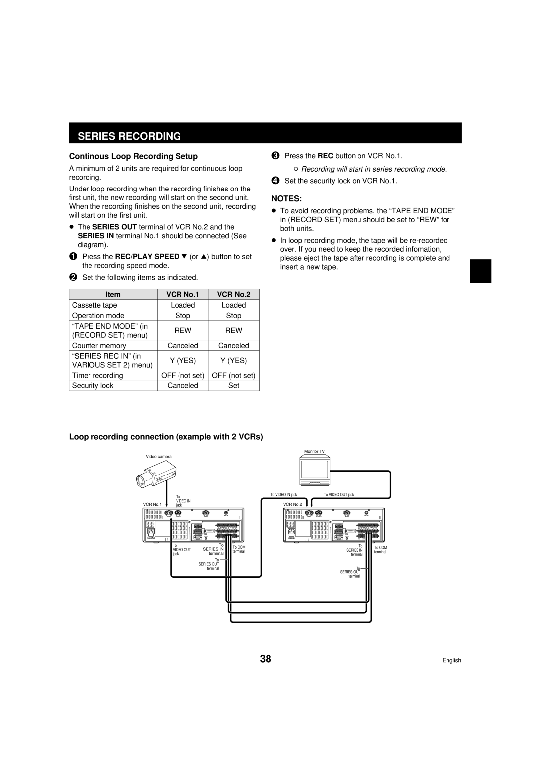
Under loop recording when the recording finishes on the first unit, the new recording will start on the second unit. When the recording finishes on the second unit, recording will start on the first unit.
œThe SERIES OUT terminal of VCR No.2 and the SERIES IN terminal No.1 should be connected (See diagram).
1Press the REC/PLAY SPEED l (or j) button to set the recording speed mode.
2Set the following items as indicated.
Item | VCR No.1 | VCR No.2 | |
Cassette tape | Loaded | Loaded | |
Operation mode | Stop | Stop | |
“TAPE END MODE” (in | REW | REW | |
(RECORD SET) menu) | |||
|
| ||
Counter memory | Canceled | Canceled | |
“SERIES REC IN” (in | Y (YES) | Y (YES) | |
VARIOUS SET 2) menu) | |||
|
| ||
Timer recording | OFF (not set) | OFF (not set) | |
Security lock | Canceled | Set | |
|
|
|
3Press the REC button on VCR No.1.
øRecording will start in series recording mode.
4Set the security lock on VCR No.1.
NOTES:
œTo avoid recording problems, the “TAPE END MODE” in (RECORD SET) menu should be set to “REW” for both units.
œIn loop recording mode, the tape will be
Loop recording connection (example with 2 VCRs)
Monitor TV
Video camera
| To | To VIDEO IN jack | To VIDEO OUT jack |
VCR No.1 | VIDEO IN | VCR No.2 |
|
jack |
|
IN OUT | IN OUT |
| IN OUT |
| MIC IN |
| IN OUT | IN OUT | |
VIDEO |
| AUDIO |
|
|
|
| VIDEO | ||
| A RS485 B |
|
|
|
|
|
|
| |
| ADDRESS |
| TERMINATE | EXT TIMER WARNING TAPE SW | COM NON REC V.LOSS |
| |||
| ON | 485 | ON |
|
|
|
|
|
|
|
|
| PUSH | IN OUT | COM | IN OUT | COM IN | OUT |
|
|
|
| CLOCK SET |
| SERIES |
| EJECT |
| |
| OFF | 232 OFF OPEN |
|
|
|
|
|
| |
AC IN |
|
| REMOTE |
|
|
|
| AC IN |
|
|
|
| ALARM | TRIGGER | IN | OUT |
| ||
| RS232C |
| RESET | SHOT REC | ALARM |
|
| ||
|
| IN | IN |
|
|
|
| ||
| To |
|
| To |
| To COM |
| ||
| VIDEO OUT |
| SERIES IN |
|
| ||||
|
|
| terminal |
| |||||
| jack |
|
| terminal |
|
| |||
|
|
|
|
|
|
| |||
To
SERIES OUT terminal
|
| IN OUT |
| MIC IN |
|
| |
|
| AUDIO |
|
|
|
|
|
A RS485 B |
|
|
|
|
|
| |
ADDRESS |
| TERMINATE | EXT TIMER WARNING TAPE SW | COM NON REC V.LOSS | |||
ON | 485 | ON |
|
|
|
|
|
|
| PUSH | IN OUT | COM | IN OUT | COM IN | OUT |
|
| CLOCK SET |
| SERIES | EJECT | ||
OFF | 232 OFF OPEN |
|
|
|
|
| |
|
| REMOTE |
|
|
|
|
|
|
|
| ALARM | TRIGGER | IN | OUT |
|
RS232C |
| RESET | SHOT REC | ALARM |
| ||
| IN | IN |
|
|
| ||
|
|
| To |
|
|
| To COM |
|
| SERIES IN |
|
|
| ||
|
|
|
|
| terminal | ||
|
|
| terminal |
|
|
| |
|
|
|
|
|
|
| |
To
SERIES OUT terminal
38 | English |
