DIGITAL OUTPUT
5.4 Output Signal List
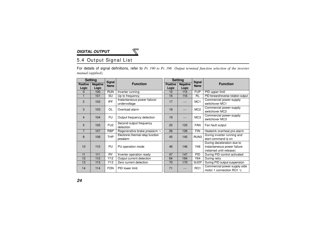
For details of signal definitions, refer to Pr. 190 to Pr. 196 Output terminal function selection of the inverter manual (applied).
Setting | Signal | Function |
| Setting | Signal | Function | ||
Positive | Negative |
| Positive | Negative | ||||
Logic | Logic | Name |
|
| Logic | Logic | Name |
|
0 | 100 | RUN | Inverter running |
| 15 | 115 | FUP | PID upper limit |
1 | 101 | SU | Up to frequency |
| 16 | 116 | RL | PID forward/reverse rotation output |
2 | 102 | IPF | Instantaneous power failure/ |
| 17 | | MC1 | Commercial |
undervoltage |
| switchover MC1 | ||||||
|
|
|
|
|
|
| ||
3 | 103 | OL | Overload alarm |
| 18 | | MC2 | Commercial |
| switchover MC2 | |||||||
|
|
|
|
|
|
|
| |
4 | 104 | FU | Output frequency detection |
| 19 | | MC3 | Commercial |
| switchover MC3 | |||||||
|
|
|
|
|
|
|
| |
5 | 105 | FU2 | Second output frequency |
| 25 | 125 | FAN | Fan fault output |
detection |
| |||||||
|
|
|
|
|
|
|
| |
7 | 107 | RBP | Regenerative brake prealarm *1 |
| 26 | 126 | FIN | Heatsink overheat |
8 | 108 | THP | Electronic thermal relay function |
| 45 | 145 | RUN3 | During inverter running and |
|
|
| prealarm |
|
|
|
| start command is on |
|
|
|
|
|
|
|
| During deceleration due to |
10 | 110 | PU | PU operation mode |
| 46 | 146 | Y46 | instantaneous power failure |
|
|
|
|
|
|
|
| (retained until release) |
11 | 111 | RY | Inverter operation ready |
| 47 | 147 | PID | During PID control activated |
12 | 112 | Y12 | Output current detection |
| 64 | 164 | Y64 | During retry |
13 | 113 | Y13 | Zero current detection |
| 70 | 170 | SLEEP | During PID output suspension |
14 | 114 | FDN | PID lower limit |
| 71 | | RO1 | |
| motor 1 connection RO1 *2 | |||||||
|
|
|
|
|
|
|
| |
24
