Barracuda 36ES2 Product Manual, Rev. B |
|
| 71 | ||
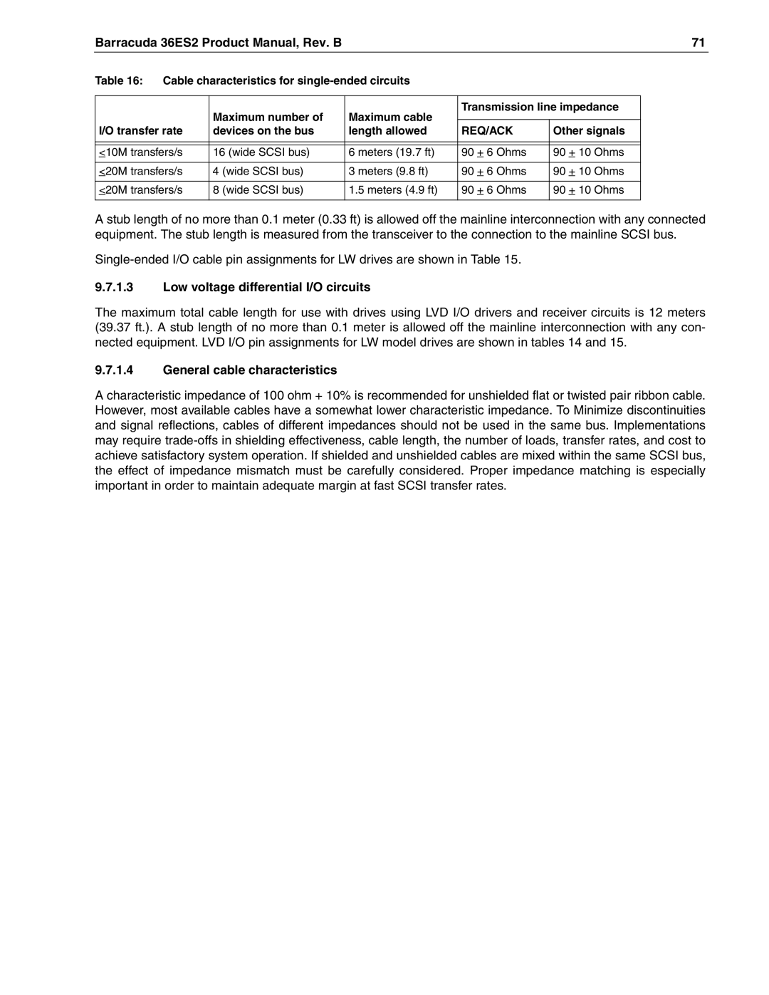
Table 16: Cable characteristics for |
|
|
| ||
|
|
|
|
|
|
| Maximum number of | Maximum cable | Transmission line impedance |
| |
|
|
|
| ||
I/O transfer rate | devices on the bus | length allowed | REQ/ACK | Other signals |
|
|
|
|
|
|
|
|
|
|
|
|
|
<10M transfers/s | 16 (wide SCSI bus) | 6 meters (19.7 ft) | 90 + 6 Ohms | 90 + 10 Ohms |
|
|
|
|
|
|
|
<20M transfers/s | 4 (wide SCSI bus) | 3 meters (9.8 ft) | 90 + 6 Ohms | 90 + 10 Ohms |
|
|
|
|
|
|
|
<20M transfers/s | 8 (wide SCSI bus) | 1.5 meters (4.9 ft) | 90 + 6 Ohms | 90 + 10 Ohms |
|
|
|
|
|
|
|
A stub length of no more than 0.1 meter (0.33 ft) is allowed off the mainline interconnection with any connected equipment. The stub length is measured from the transceiver to the connection to the mainline SCSI bus.
9.7.1.3Low voltage differential I/O circuits
The maximum total cable length for use with drives using LVD I/O drivers and receiver circuits is 12 meters (39.37 ft.). A stub length of no more than 0.1 meter is allowed off the mainline interconnection with any con- nected equipment. LVD I/O pin assignments for LW model drives are shown in tables 14 and 15.
9.7.1.4General cable characteristics
A characteristic impedance of 100 ohm + 10% is recommended for unshielded flat or twisted pair ribbon cable. However, most available cables have a somewhat lower characteristic impedance. To Minimize discontinuities and signal reflections, cables of different impedances should not be used in the same bus. Implementations may require