ST336938LW
Product Manual, Volume
Barracuda 36ES2 Family
ST336918N
Page
ST336938LW
Product Manual, Volume
Barracuda 36ES2 Family
ST336918N
Page
Writer/Engineer
Revision status summary sheet
Revision
Date
Page
6.0 Physical/electrical specifications
Contents
4.0 Performance characteristics
5.0 Reliability specifications
9.0 Interface requirements
7.0 Defect and error management
8.0 Installation
10.0 Seagate Technology support services
Barracuda 36ES2 Product Manual, Rev. B
List of Figures
Page
Barracuda 36ES2 Product Manual, Rev. B
1.0 Scope
Figure 1. Barracuda 36ES2 family drive ST336938LW shown
Barracuda 36ES2 Product Manual, Rev. B
2.1.2 Electromagnetic susceptibility
2.0 Applicable standards and reference documentation
2.1 Standards
2.1.1 Electromagnetic compatibility
Reference documents
Australian C-Tick
Korean MIC
Taiwanese BSMI
Barracuda 36ES2 Product Manual, Rev. B
3.0 General description
3.4 Reliability
3.1 Standard features
3.2 Media characteristics
3.3 Performance
3.6 Programmable drive capacity
3.7 Factory installed accessories
3.8 Options factory installed
3.5 Unformatted and formatted capacities
4.2.1 Access time
4.0 Performance characteristics
4.1 Internal drive characteristics transparent to user
4.2 SCSI performance characteristics visible to user
4.3 Start/stop time
Ultra2 SCSI
Ultra160 SCSI
Notes for Section
Barracuda 36ES2 Product Manual, Rev. B
4.5 Cache operation
4.5.1 Caching write data
In general, 2,048 Kbytes of the physical buffer space in the drive can be used as storage space for cache oper- ations. The buffer can be divided into logical segments Mode Select Page 08h, byte 13 from which data is read and to which data is written. The drive maintains a table of logical block disk medium addresses of the data stored in each segment of the buffer. If cache operation is enabled RCD bit = 0 in Mode Page 08h, byte 2, bit 0. See SCSI Interface Product Manual, part number 75789509, data requested by the host with a Read command is retrieved from the buffer if it is there, before any disc access is initiated. If cache operation is not enabled, the buffer still segmented with required number of segments is still used, but only as circular buffer segments during disc medium read operations disregarding Prefetch operation for the moment. That is, the drive does not check in the buffer segments for the requested read data, but goes directly to the medium to retrieve it. The retrieved data merely passes through some buffer segment on the way to the host. On a cache miss, all data transfers to the host are in accordance with buffer-full ratio rules. On a cache hit the drive ignores the buffer-full ratio rules. See explanations associated with Mode page 02h disconnect/reconnect control in the SCSI Interface Product Manual
Tables 8 and 9 show Mode default settings for the drives
4.5.2 Prefetch operation
Barracuda 36ES2 Product Manual, Rev. B
Barracuda 36ES2 Product Manual, Rev. B
5.1.3 Write errors
5.0 Reliability specifications
5.1 Error rates
5.1.2 Read errors
5.2.4 Service philosophy
5.2 Reliability and service
5.2.2 Preventive maintenance
5.2.3 Service life
Case 1 - All bus devices powered off during removal or insertion
5.2.6 Hot plugging Barracuda 36ES2 disc drives
5.2.7 S.M.A.R.T
Controlling S.M.A.R.T
Predictive failures
Performance impact
Reporting control
Determining rate
5.2.8.2.2 Invoking DST
5.2.8.2.1 State of the drive prior to testing
5.2.8.1 DST Failure Definition
5.2.8.2 Implementation
5.2.8.2.4 Log page entries
5.2.9 Product warranty
Short test Function Code 001b
Extended test Function Code 010b
Barracuda 36ES2 Product Manual, Rev. B
Product repair and return information
Seagate repair centers may refuse receipt of components improperly packaged or obviously damaged in tran- sit. Contact your Authorized Seagate Distributor to purchase additional boxes. Seagate recommends shipping by an air-ride carrier experienced in handling computer equipment
Barracuda 36ES2 Product Manual, Rev. B
Barracuda 36ES2 Product Manual, Rev. B
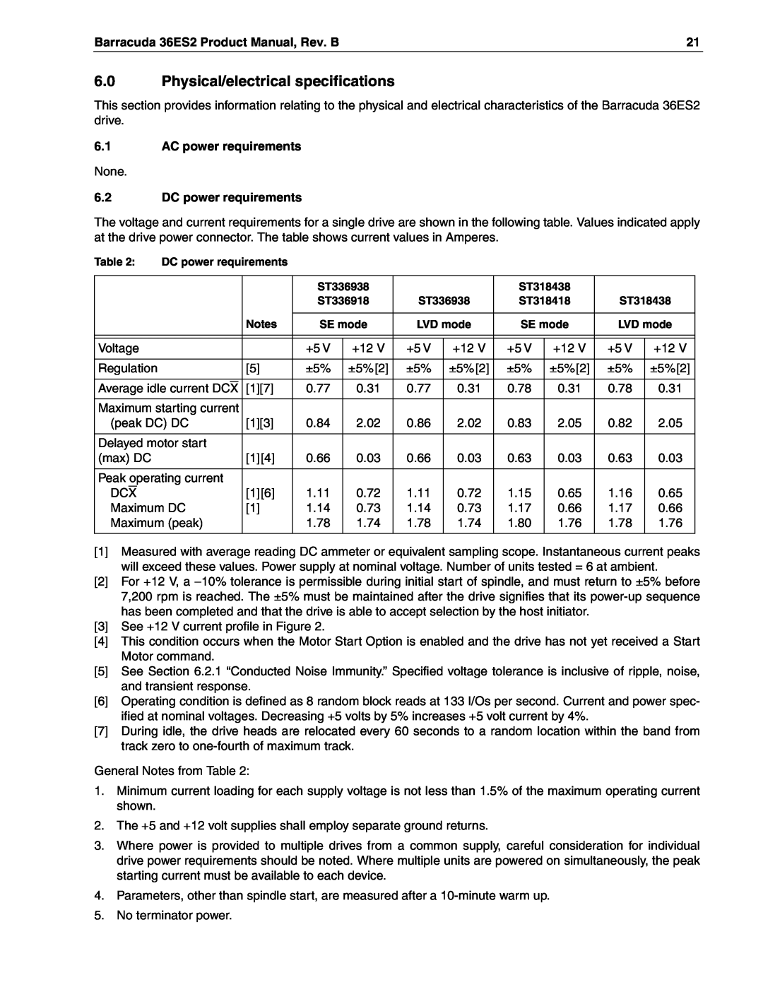
6.0 Physical/electrical specifications
6.1 AC power requirements
6.2 DC power requirements
Barracuda 36ES2 Product Manual, Rev. B
6.2.2 Power sequencing
6.2.1 Conducted noise immunity
6.2.3 12 V - Current profile
Nominal average DC curve
Barracuda 36ES2 Product Manual, Rev. B
+5 Volt Current during spindle start - Typical Amper es
Amps
Watts
6.3 Power dissipation ST336938/ST318438
Barracuda 36ES2 Product Manual, Rev. B
Amperes
Watts
ST336918/ST318418
Barracuda 36ES2 Product Manual, Rev. B
Amperes
a. Operating
6.4.1 Temperature
6.4 Environmental limits
Barracuda 36ES2 Product Manual, Rev. B
6.4.4.1 Shock
6.4.2 Relative humidity
6.4.3 Effective altitude sea level
6.4.4 Shock and vibration
Figure 7. Recommended mounting
Barracuda 36ES2 Product Manual, Rev. B
Z X YZ Y X
6.4.7 Electromagnetic susceptibility
6.4.5 Air cleanliness
6.4.4.2 Vibration
6.4.6 Acoustics
Barracuda 36ES2 Product Manual, Rev. B
6.5 Mechanical specifications
Height
Dimension Table
Figure 9. N mounting configuration dimensions
Barracuda 36ES2 Product Manual, Rev. B
Barracuda 36ES2 Product Manual, Rev. B
Barracuda 36ES2 Product Manual, Rev. B
7.0 Defect and error management
7.2 Drive error recovery procedures
7.1 Drive internal defects
Barracuda 36ES2 Product Manual, Rev. B
7.3 SCSI systems errors
1 These values are subject to change
8.1 Drive ID/option select header
8.0 Installation
Configure drive options
Formatting
Do not install jumpers retain cover
Shipped with cover installed
Barracuda 36ES2 Product Manual, Rev. B
Drive Activity LED
Shipped with cover installed
Do not install jumpers retain cover
Barracuda 36ES2 Product Manual, Rev. B
Usage Plug
Barracuda 36ES2 Product Manual, Rev. B
Host
Alternate
Jumper Positions
Barracuda 36ES2 Product Manual, Rev. B
Figure 13. J2 option select header for LW models
Figure 14. J2 option select header for N models
2 These signals are also on J1 I/O connector J5, Pins 1-12. See Figure
8.1.1 Notes for Figures 14 through
Barracuda 36ES2 Product Manual, Rev. B
jumper
8.1.2 Function description
installation
Barracuda 36ES2 Product Manual, Rev. B
Barracuda 36ES2 Product Manual, Rev. B
8.1.3 Drive orientation
8.2 Cooling
8.2.1 Air flow
k * x = F 15lb = 67N
8.3 Drive mounting
8.4 Grounding
Barracuda 36ES2 Product Manual, Rev. B
Barracuda 36ES2 Product Manual, Rev. B
Barracuda 36ES2 Product Manual, Rev. B
9.0 Interface requirements
9.1 General description
9.2 SCSI interface messages supported
Barracuda 36ES2 Product Manual, Rev. B
9.3 SCSI interface commands supported
Barracuda 36ES2 Product Manual, Rev. B
Barracuda 36ES2 Product Manual, Rev. B
Data HEX
Barracuda 36ES2 Product Manual, Rev. B
Table 6 Barracuda 36ES2 family drive Standard Inquiry data
Bytes
Firmware numbers page C0h
9.3.1 Inquiry Vital Product data
Unit serial number page 80h
Implemented operating definition page 81h
Barracuda 36ES2 Product Manual, Rev. B
Jumper settings page C2h
The Mode Sense command provides a means for the drive to report its operating parameters to the initiator. The drive maintains four sets of Mode parameters, Default values, Saved values, Current values and Change- able values
9.3.2 Mode Sense data
Barracuda 36ES2 Product Manual, Rev. B
Definitions
Barracuda 36ES2 Product Manual, Rev. B
Barracuda 36ES2 Product Manual, Rev. B
Mode Page 10 Byte Header Data and Parameter Data Bytes
Condition/features supported
9.4 SCSI bus conditions and miscellaneous features supported
Barracuda 36ES2 Product Manual, Rev. B
Supported
Conditions or feature
Barracuda 36ES2 Product Manual, Rev. B
Supported
9.5.2 REQ/ACK offset
9.6.1 DC cable and connector
9.5 Synchronous data transfer
9.5.1 Synchronous data transfer periods supported
Power
Figure 16. N model drive physical interface 50-pin SCSI I/O connector
Barracuda 36ES2 Product Manual, Rev. B
Barracuda 36ES2 Product Manual, Rev. B
Power
Table 12 Interface transfer rates supported
9.6.2 SCSI interface physical description
9.6.3 SCSI interface cable requirements
Barracuda 36ES2 Product Manual, Rev. B
Mating panel mount connector 3M -CHE-2050-J01A10-KLE
9.6.4 Mating connectors
9.6.4.1 Mating connectors for N model drives
with adjacent pins 100 mils apart. The connector is keyed see Figure
Barracuda 36ES2 Product Manual, Rev. B
1 Closed end type 50-pin connector used. Terminators enabled
Barracuda 36ES2 Product Manual, Rev. B
9.6.4.2 Mating connectors for LW model drives
adapter for Pin 1 location
Barracuda 36ES2 Product Manual, Rev. B
Figure 21. SCSI daisy chain interface cabling for LW drives
check your
Barracuda 36ES2 Product Manual, Rev. B
Barracuda 36ES2 Product Manual, Rev. B
Barracuda 36ES2 Product Manual, Rev. B
9.7.1 Multimode-SE and LVD alternatives
Multimode signals
Notes for Tables 13 through
9.7 Electrical description
voltage
Output characteristics
Input characteristics
Barracuda 36ES2 Product Manual, Rev. B
9.7.1.2 Single-ended drivers/receivers for LW models
Transmitter characteristics
Receiver characteristics
9.7.1.1 Single-ended drivers/receivers for N models
Other signals
9.7.1.4 General cable characteristics
9.7.1.3 Low voltage differential I/O circuits
Table 16 Cable characteristics for single-ended circuits
1. Drive accepts terminator power through SCSI bus pin 26 on N models
9.9 Terminator power N drives
9.8 Terminator requirements
LW drives
Disc drive SCSI timing
9.10
Barracuda 36ES2 Product Manual, Rev. B
Format with Immediate option on
9.11 Drive activity LED
Powered down by removal of DC power
Barracuda 36ES2 Product Manual, Rev. B
Technical Support
10.0 Seagate Technology support services Online Services
Automated Services
Presales Support
Warranty Service
Customer Service CSO
USA/Canada/Latin America Support Services
European Support Services
Warranty Service
Africa/Middle East Support Services
Asia/Pacific Support Services
FAX Services-All European Countries
Barracuda 36ES2 Product Manual, Rev. B
Barracuda 36ES2 Product Manual, Rev. B
Symbols
Index
Numerics
Barracuda 36ES2 Product Manual, Rev. B
Barracuda 36ES2 Product Manual, Rev. B
Barracuda 36ES2 Product Manual, Rev. B
Barracuda 36ES2 Product Manual, Rev. B
X3T10/1143D
write error 13 unrecoverable
Barracuda 36ES2 Product Manual, Rev. B
write operation 10 write protect 41 write retry count
Page
920 Disc Drive, Scotts Valley, California 95066-4544, USA
Seagate Technology LLC
Publication Number 100182971, Rev. B, Printed in USA