Barracuda 4LP Installation Guide, Rev. B | 41 | ||||
|
|
|
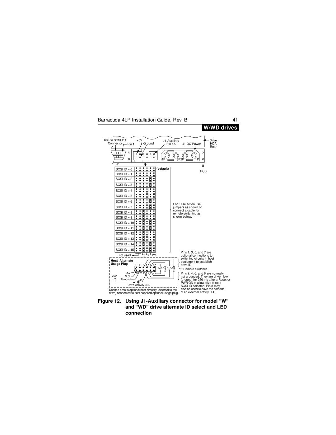
| W/WD drives | |
68 Pin SCSI I/O | +5V |
| Drive | ||
| |||||
Connector Pin 1 | Ground | Pin 1A |
| HDA | |
|
|
|
|
| Rear |
|
|
|
|
| |
4P | 3P2P | 1P |
J1 |
|
|
| SCSI ID = 0 |
|
|
|
|
| (default) |
|
| PCB | ||
| SCSI ID = 1 |
|
|
|
|
|
|
|
| |||
|
|
|
|
|
|
|
|
|
| |||
|
|
|
|
|
|
|
|
|
|
|
| |
| SCSI ID = 2 |
|
|
|
|
|
|
|
|
| ||
|
|
|
|
|
|
|
|
|
|
|
| |
| SCSI ID = 3 |
|
|
|
|
|
|
|
|
| ||
|
|
|
|
|
|
|
|
|
|
|
| |
| SCSI ID = 4 |
|
|
|
|
|
|
|
|
| ||
| SCSI ID = 5 |
|
|
|
|
|
|
|
|
| ||
| SCSI ID = 6 |
|
|
|
|
|
| For ID selection use | ||||
| SCSI ID = 7 |
|
|
|
|
|
| |||||
|
|
|
|
|
|
| jumpers as shown or | |||||
| SCSI ID = 8 |
|
|
|
|
|
| connect a cable for | ||||
|
|
|
|
|
|
| remote switching as | |||||
| SCSI ID = 9 |
|
|
|
|
|
| shown below. | ||||
| SCSI ID = 10 |
|
|
|
|
|
|
|
|
| ||
| SCSI ID = 11 |
|
|
|
|
|
|
|
|
| ||
| SCSI ID = 12 |
|
|
|
|
|
|
|
|
| ||
| SCSI ID = 13 |
|
|
|
|
|
|
|
|
| ||
| SCSI ID = 14 |
|
|
|
|
|
|
|
|
| ||
|
|
|
|
|
|
|
|
|
|
|
| |
| SCSI ID = 15 |
|
|
|
|
|
|
| Pins 1, 3, 5, and 7 are | |||
|
| not used |
|
| A3 A2 A1A0 |
| ||||||
|
|
|
|
| optional connections to | |||||||
Host | Alternate |
|
|
|
|
|
|
| switching circuits in host | |||
|
|
|
|
|
|
| equipment to establish | |||||
Usage Plug |
|
|
|
|
|
|
| |||||
11 9 7 | 5 | 3 | 1 |
|
| drive ID. | ||||||
|
|
|
| A0 A1 A2 | A3 | |||||||
|
| +5V |
|
|
|
|
|
| Remote Switches | |||
|
|
|
|
|
|
|
| |||||
|
| 12 10 8 | 6 | 4 | 2 |
|
| Pins 2, 4, 6, and 8 are normally | ||||
+5V | N.C. |
|
|
|
|
|
|
| not grounded. They are driven low | |||
|
| Ground |
|
|
|
|
|
|
| (ground) for 250 ms after a Reset or | ||
|
|
|
|
|
|
|
|
|
|
| PWR ON to allow drive to read | |
|
| Drive Activity LED |
|
|
| |||||||
|
|
|
|
| SCSI ID selected. Pin 8 may | |||||||
Dashed area is optional host circuitry (external to the | also be used to drive the cathode | |||||||||||
drive) connected to host supplied optional usage plug. | of an external Activity LED. | |||||||||||