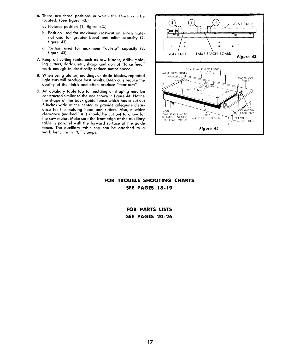
6.There are three positions in which the fence can be located. (See figure 43.)
a. Normal position (1, figure 43.)
b.Position used for maximum
rial and for greater bevel and miter capacity (2, figure 43).
c.Position used for maximum
7.Keep all cutting tools, such as saw blades, drills, mold- ing cutters, dados, etc., sharp, and do not "force feed" work enough to drastically reduce motor speed.
8.When using planer, molding, or dado blades, repeated light cuts will produce best results. Deep cuts reduce the quality of the finish and often produce
9.An auxiliary table top for molding or shaping may be constructed similar to the one shown in figure 44. Notice the shape of the back guide fence which has a
f/, FRONT TABLE
iiI
vO | v I |
REAR TABLE TABLE SPACER BOARD
Figure 43
RADIAL SAW
TABLE
LAMP ON
EACH END
SUPPORTS
I" x 2"
I
Figure 44
I
FOR TROUBLE SHOOTING CHARTS
SEE PAGES 18-19
FOR PARTS LISTS
SEE PAGES 20°26
17