| USE | OF | THE DADO | HEAD |
|
|
| |||||
The dado saw (or head) is a special set of blades for cutting | 7 | |||||||||||
grooves and dados. The Craftsman | ||||||||||||
Set may be purchased at any Sears Retail Store or Catalog | ||||||||||||
Order | House. The complete | head consists of | two outside | |||||||||
blades |
| |||||||||||
and paper washers for |
| |||||||||||
these blades, grooves may be made in widths of |
| |||||||||||
| ||||||||||||
| ||||||||||||
blades may be used alone, but chippers cannot be used |
| |||||||||||
alone. When the maximum |
| |||||||||||
used on the motor shaft, the outside loose collar must not |
| |||||||||||
be used. The width of the dado can be reduced while using |
| |||||||||||
the loose collar and two or more passes may be made with |
| |||||||||||
the work to obtain the desired width of cut. Whenever two |
| |||||||||||
or more chippers are used, the cutting ends should be | Figure 35 | |||||||||||
staggered as evenly as possible around the circumference. | ||||||||||||
| ||||||||||||
Fractional adjustments in thickness of the head can be |
| |||||||||||
made by using paper washers between the | outside blades |
| ||||||||||
and chippers. |
|
|
|
|
|
|
|
|
| |||
Dado | head | operations | are | essentially the | same as | those |
| |||||
operations | using | a standard | saw | the | dado |
| ||||||
head takes a bigger bite, therefore, the |
| |||||||||||
be held more firmly. When a groove wider than the dado |
| |||||||||||
head is needed, make two or more passes, with cuts spaced |
| |||||||||||
to overlap a trifle. Dado work is performed in the |
| |||||||||||
position. Ploughing is done in the ripping position. If the |
| |||||||||||
rip or plough position is used, the saw guard and anti- |
| |||||||||||
kickback pawl assembly should be adjusted as described |
| |||||||||||
in the paragraph "RIPPING". Rabbeting is done with the |
| |||||||||||
motor shaft in a vertical position. (See figure 35.) When |
| |||||||||||
rabbeting, the motor is indexed 90 ° to the vertical position |
| |||||||||||
so the blades are between the table top and motor, and |
| |||||||||||
the yoke is indexed 90 ° clockwise and locked. The saw |
| |||||||||||
is moved back on the radial arm and locked to the arm |
| |||||||||||
when the amount of the blade extending forward of the |
| |||||||||||
fence | is equal to | the | depth | of | the | rabbet | desired. | If the | BRAKE | |||
depth | of the rabbet is large, | do | not | attempt | to | cut it | in one | BRAKE | ||||
operation. | Lower | the radial arm | until | blades are in a | DRUM | HOUSING | |||||
|
| ASSEMBLY | |||||||||
position to | cut the | desired | width | of | rabbet in the | edge | of |
|
|
| |
the board. | The discharge | elbow | should | be directed | to | the |
|
|
| ||
rear of the saw.
MOLDING OR SHAPING
This work is performed with Craftsman Molding Cutter Heads, and a set of cutters depending on the type of mold- ing cut desired. The saw is positioned in the same manner as that described for rabbeting. (See figure 36.) Since the position of the cutters can be adjusted with respect to the
fence and table top, any or all of the cutter shapes may be used.
The Molding Cutter Guard should be used with Molding Cutter Head.
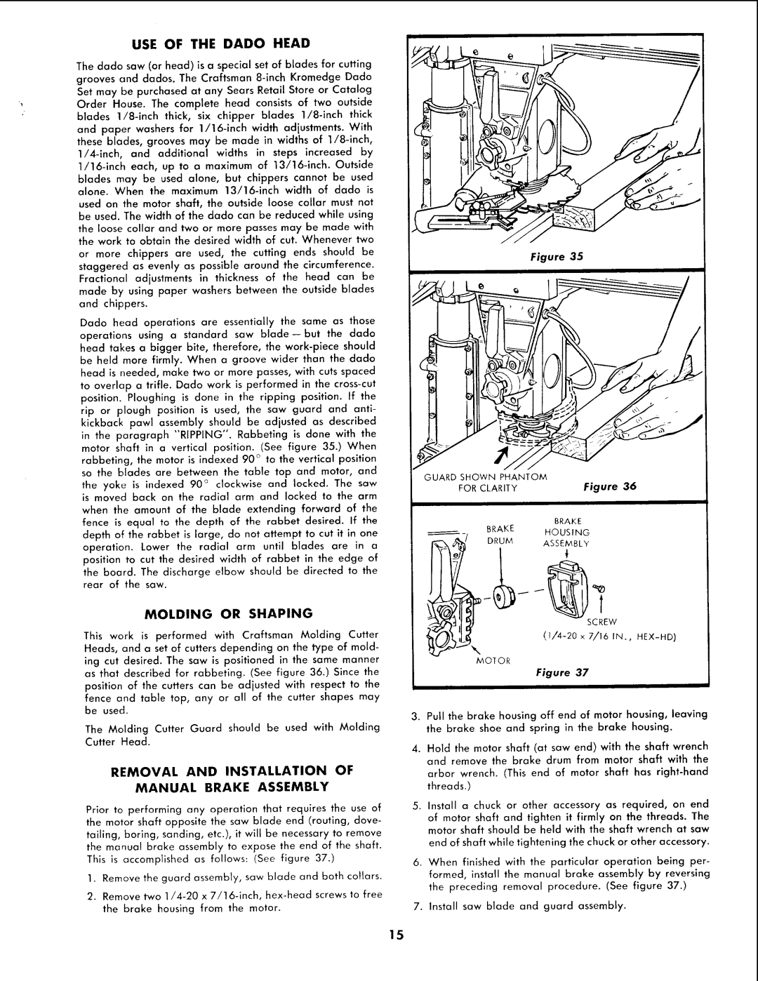
REMOVAL AND INSTALLATION OF
MANUAL BRAKE ASSEMBLY
Prior to performing any operation that requires the use of the motor shaft opposite the saw blade end (routing, dove- tailing, boring, sanding, etc.), it will be necessary to remove the manual broke assembly to expose the end of the shaft.
This is accomplished as follows: (See figure 37.)
1.Remove the guard assembly, saw blade and both cottars.
2.Remove two
w
MOTOR
Figure 37
I
3.Pull the brake housing off end of motor housing, leaving the brake shoe and spring in the brake housing.
4.Hold the motor shaft (at saw end) with the shaft wrench and remove the brake drum from motor shaft with the arbor wrench. (This end of motor shaft has
5.Install a chuck or other accessory as required, on end of motor shaft and tighten it firmly on the threads. The motor shaft should be held with the shaft wrench at saw
end of shaft while tightening the chuck or other accessory.
6.When finished with the particular operation being per- formed, install the manual brake assembly by reversing
the preceding removal procedure. (See figure 37.)
7.Install saw blade and guard assembly.
15