| BOTTOM | SIDE | OF | TABLE | REAR | TABLE |
|
|
|
| SUPPORT | BRACKET | |
|
|
|
| FRONT |
|
|
|
|
|
| TABLE |
|
|
CORRECTLY | INSTALLED |
|
|
|
| |
|
|
|
|
| Q,I |
|
LEVELING | SCRTW |
|
|
|
|
|
| TOP OF | TABLE |
|
| ||
|
|
|
|
|
| |
|
|
|
|
| SCREW | |
BASE | LEVELING | SCREW | (No. | 10 x | 5/8 IN.) | |
INSTALLED |
|
| ||||
IN
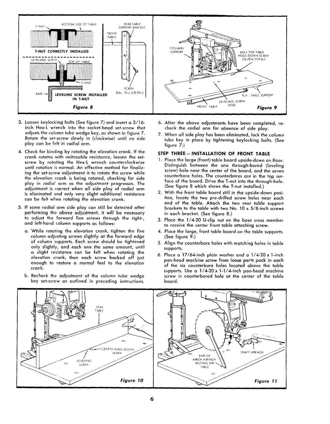
Figure 8
3.Loosen keylocking bolts (See figure 7) and insert a 3/16- inch
adjusts the column tube wedge key, as shown in figure 7. Rotate the
4.Check for binding by rotating the elevation crank. If the crank rotates with noitceable resistance, loosen the set-
screw by rotating the
ing the
5.If some radial arm side play can still be detected after performing the above adjustment, it will be necessary
to adjust the forward five screws through the
a.While rotating the elevation crank, tighten the five column adjusting screws slightly at the forward edge of column supports. Each screw should be tightened only slightly, and each one the same amount, until a slight resistance can be felt when rotating the elevation crank, then each screw backed off just
enough to restore a normal feel to the elevation crank.
b.Recheck the adjustment of the column tube wedge key
Figure 10
COLUMN |
|
|
SUPPORT | HOLE FOR | TABLE |
| SCREW | |
| (SEVEN,TOTAL) | |
| R.H. TABLE SUPPORT | |
| LEVELING SCREW | |
FRONT TABLE | HOLE | |
Figure 9 | ||
|
6.After the above adjustments have been completed, re- check the radial arm for absence of side play.
7.When all side play has been eliminated, lock the column tube key in place by tightening keylocking bolts. (See figure 7.)
STEP THREE--INSTALLATION OF FRONT TABLE
1.Place the large (front) table board
(See figure 8 which shows the
2.With the front table board still in the
3.Place the
4.Place the large, front table board on the table supports. (See figure 9.)
5.Align the counterbore holes with matching holes in table supports.
6.Place a
supports. Use a
Figure 1 1
ii