c. If the saw blade moves away from the square as it comes forward, loosen the front arm latch screw and tighten the rear arm latch screw. Recheck blade travel and repeat if necessary.
d. If the saw blade moves toward the square as it comes forward, loosen the rear arm latch screw and tighten the front arm latch screw. Recheck blade travel and repeat if necessary.
e. When the adjustment is correct, both arm latch screws should be snug against the arm latch handle but not tight enough to bind the handle.
f. Tighten the
g. Adjust indicator scale, as described in preceding paragraph 6.
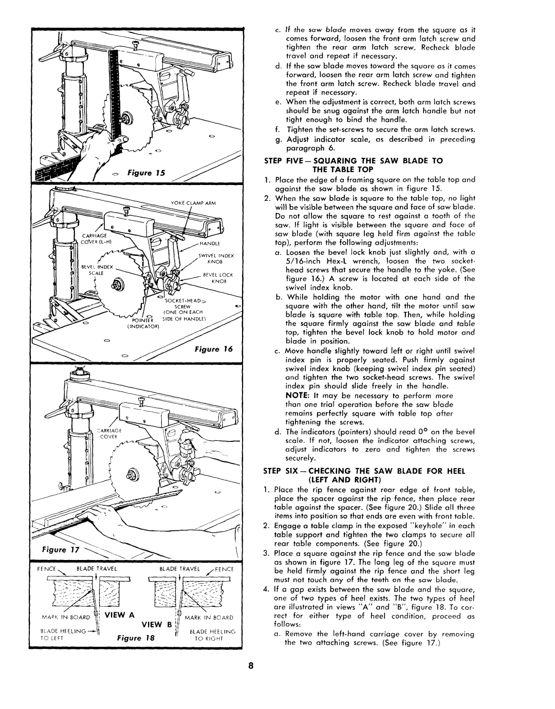
STEP FIVE--SQUARING THE SAW BLADE TO
Figure 15
THE TABLE TOP
1. Place the edge of a framing square on the table top and against the saw blade as shown in figure 15.
2. When the saw blade is square to the table top, no light will be visible between the square and face of saw blade. Do not allow the square to rest against a tooth of the saw. If light is visible between the square and face of saw blade (with square leg held firm against the table top), perform the following adjustments:
a. Loosen the bevel lock knob just slightly and, with a
head screws that secure the handle to the yoke. (See
figure 16.) A screw is located at each side of the swivel index knob.
b. While holding the motor with one hand and the square with the other hand, tilt the motor until saw blade is square with table top. Then, while holding the square firmly against the saw blade and table top, tighten the bevel lock knob to hold motor and blade in position.
|
|
|
| Figure 16 | c. Move | handle | slightly | toward | left | or | right | until | swivel | |||||||||
|
|
|
|
|
| index pin is properly seated. Push firmly against | ||||||||||||||||
|
|
|
|
|
| swivel index knob (keeping swivel index pin seated) | ||||||||||||||||
|
|
|
|
|
| and tighten the two | ||||||||||||||||
|
|
|
|
|
| index pin should slide freely in the handle. |
|
| ||||||||||||||
|
|
|
|
|
| NOTE: It may be necessary to perform more |
| |||||||||||||||
|
|
|
|
|
| than one trial operation before the saw blade |
| |||||||||||||||
|
|
|
|
|
| remains perfectly square with table top after |
| |||||||||||||||
|
|
|
|
|
| tightening the screws. |
|
|
|
|
|
|
|
|
| |||||||
|
|
|
|
| d. | The | indicators (pointers) should read 0 ° on the bevel | |||||||||||||||
|
|
|
|
|
| scale. If not, loosen the indicator attaching screws, | ||||||||||||||||
|
|
|
|
| adjust indicators to zero and tighten the screws | |||||||||||||||||
|
|
|
|
|
| securely. |
|
|
|
|
|
|
|
|
|
|
|
| ||||
|
|
|
| STEP |
| THE SAW BLADE FOR HEEL | ||||||||||||||||
|
|
|
|
|
|
|
|
| (LEFT | AND | RIGHT) |
|
|
|
|
|
|
|
|
| ||
|
|
|
| 1. | Place the rip fence against | rear | edge |
| of | front |
| table, | ||||||||||
|
|
|
|
| place the spacer against the rip fence, then place rear | |||||||||||||||||
|
|
|
|
| table against the spacer. (See figure 20.) Slide all three | |||||||||||||||||
|
|
|
|
| items | into | position so that ends are even with front table. | |||||||||||||||
|
|
|
| 2. | Engage |
| a | table | clamp | in the | exposed | "'keyhole" | in | each | ||||||||
|
|
|
|
| table support and tighten the two clamps to secure all | |||||||||||||||||
Figure | 17 |
|
|
| rear |
| table | components. |
| (See | figure | 20.) |
|
|
|
| ||||||
|
| 3. | Place | a |
| square | against | the rip fence and the saw blade | ||||||||||||||
|
|
|
|
| ||||||||||||||||||
• I |
|
|
|
| as shown in figure 17. The long leg of the square must | |||||||||||||||||
|
|
|
|
| ||||||||||||||||||
FENCE,,,,,.,, | BLADE TRAVEL |
| BLADE | TRAVEL //FENCE | be | held | firmly | against |
| the rip fence and the short leg | ||||||||||||
|
|
|
|
| must | not | touch | any of the teeth on the saw blade. |
| |||||||||||||
|
|
|
| 4. | If a | gap | exists | between |
| the saw | blade | and | the | square, | ||||||||
|
|
|
|
| one of two types of heel exists. The two types of heel | |||||||||||||||||
|
|
|
|
| are illustrated in views "A" and "B", figure 18. To cor- | |||||||||||||||||
|
|
|
|
| rect |
| for | either | type | of heel | condition, |
| proceed | as | ||||||||
BLADE.E EL,.O |
| VIEW Bill | MARr._LADE,NHEEL,NGBOARD | follows: |
|
|
|
|
|
|
|
|
|
|
|
|
|
|
| |||
| a. | Remove | the | carriage |
| cover | by removing | |||||||||||||||
To C[FT |
| Figure | 18 | TO RIOHT |
| |||||||||||||||||
| the | two | attaching | screws. | (See | figure | 17.) |
|
| |||||||||||||
|
|
|
|
|
|
| ||||||||||||||||
II
8