b. Loosen the yoke clamp arm. (See figure 16.1
c. Loosen (slightly) the two
d. With the square in position shown in figure 17, shift the yoke until the gap between the saw blade and square is eliminated.
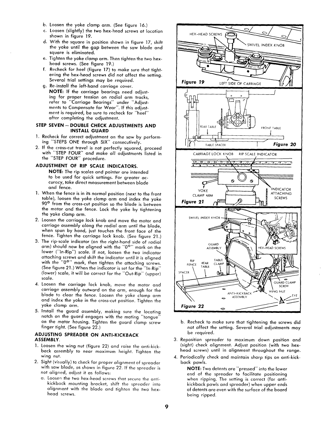
e. Tighten the yoke clamp arm. Then tighten the two hex- head screws. (See figure 19.)
f.Recheck for heel (figure 17) to make sure that tight- ening the
Several trial settings may be required. g.
NOTE: If the carriage bearings need adjust- ing for proper tension on radial arm tracks,
refer to "Carriage Bearings °' under "Adjust° ments to Compensate for Wear". If this adjust- ment is required, be sure to recheck for "heel"
after completing the adjustment.
STEP SEVEN- DOUBLE CHECK ADJUSTMENTS AND INSTALL GUARD
1.Recheck for correct adjustment on the saw by perform- ing "STEPS ONE through SIX" consecutively.
2.If the
ADJUSTMENT OF RIP SCALE INDICATORS.
NOTE: The rip scales and pointer are intended to be used for quick settings. For greater ac-
curacy, take direct measurement between blade and fence.
1.When the fence is in its normal position (next to the front table), loosen the yoke clamp arm and index the yoke 90 ° from the
the mator and the fence. Lock the yoke by tightening the yoke clamp arm.
2.Loosen the carriage lock knob and move the motor and carriage assembly along the radial arm until the blade, when spun by hand, just touches the front face of the fence. Tighten the carriage lock knob. (See figure 21.)
3.The
lower
attaching screws and shift the indicator until it is aligned with the "0 °'° mark, then tighten the attaching screws. (See figure 21 .) When the indicator is set for the
(lower) scale, it will be correct for the
4.Loosen the carriage lock knob, move the motor and carriage assembly outward on the arm, enough for the blade to clear the fence. Loosen the yoke clamp arm and index the yoke in the
5.Install the guard assembly, making sure the locating notch on the guard engages with the mating "tongue" on the motor housing. Tighten the guard clamp screw finger tight. (See figure 22.)
ADJUSTING SPREADER ON ANTI-KICKBACK
ASSEMBLY.
1.Loosen the wing nut (figure 22) and raise the
back assembly to near maximum height. Tighten the wing nut.
2.Sight (visually) to check for proper alignment of spreader with saw blade, as shown in figure 22. If the spreader is not aligned, adjust it as follows:
a.Loosen the two
kickback mounting bracket, shift the spreader into
alignment with the blade and tighten the two hex- head screws.
i | i |
HEX_HEAD__
Figure/
E
_k:d |
| " | I |
. | TABLESPACER |
| Figure 20 |
CARRIAGE LOCK KNOB RIP SCALE INDICATOR
•Z
÷"' It" '''_'''_''_'"_''"I_"'
| _ | / | _INDICATOR |
YOKE | __ | :_ | ATTACHING |
CLAMP ARMI- | SCREWS | ||
Figure 21 | __//________ |
|
|
-
Figure 22 | _=_ | _ | _ |
b. Recheck to make sure that tightening the screws did not affect the setting. Several trial adjustments may be required.
3. Reposition spreader to maximum down position and
(sight) check alignment. Adjust position (with two hex-
head screws) until in alignment throughout the range.
4.Periodically check and maintain sharp tips on
NOTE: Two deents are "pressed" into the lower
end of the spreader to facilitate positioning when ripping. The setting is correct (for anti- kickback pawls and spreader) when upper ends of detents are even with the surface of the board being ripped.
9