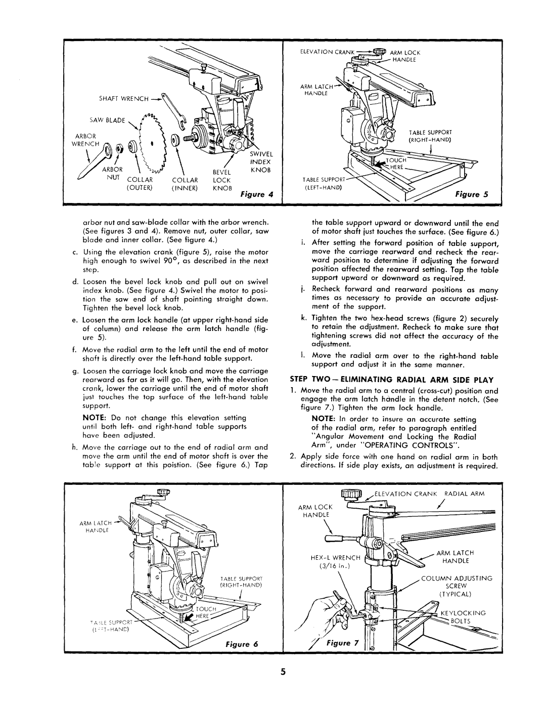
SHAFT WRENCH
SAW BLADE
ARBOR |
|
|
|
|
|
|
|
| SWIVEL |
// | AR OR |
|
| INDEX |
\ | BEVEL | KNOB | ||
zJ | NUT COLLAR | COLLAR | LOCK |
|
| (OUTER) | (INNER) | KNOB | Figure 4 |
|
|
|
|
arbor nut and
(See figures 3 and 4). Remove nut, outer collar, saw blade and inner collar. (See figure 4.)
c. Using the elevation crank (figure 5), raise the motor high enough to swivel 90 ° , as described in the next step.
d. Loosen the bevel lock knob and pull out on swivel index knob. (See figure 4.) Swivel the motor to posi-
tion the saw end of shaft pointing straight down. Tighten the bevel lock knob.
e. Loosen the arm lock handle (at upper
f.Move the radial arm to the left until the end of motor shaft is directly over the
g.Loosen the carriage lock knob and move the carriage rearward as far as it will go. Then, with the elevation
crank, lower the carriage until the end of motor shaft
just touches the top surface of the
NOTE: Do not change this elevation setting
until both left- and
h.Move the carriage out to the end of radial arm and move the arm until the end of motor shaft is over the
table support at this poistion. (See figure 6.) Tap
ii
ARM LATCH "_"% / _'_
\
HANDLE
< _ | ° rOUCH |
TA _LE SUPPORT
Figure 6
ELEVATION CRANK | ARM LOCK |
| HANDLE |
ARM |
|
HANDLE |
|
TABLE SUPPORT
TABLE
Figure 5
the table support upward or downward until the end of motor shaft just touches the surface. (See figure 6.)
i. After setting the forward position of table support, move the carriage rearward and recheck the rear-
ward position to determine if adjusting the forward position affected the rearward setting. Tap the table support upward or downward as required.
j. Recheck forward and rearward positions as many times as necessary to provide an accurate adjust- ment of the support.
k. Tighten the two
I. Move the radial arm over to the
STEP TWO--ELIMINATING RADIAL ARM SIDE PLAY
1.Move the radial arm to a central
NOTE: In order to insure an accurate setting of the radial arm, refer to paragraph entitled "Angular Movement and Locking the Radial Arm", under "OPERATING CONTROLS".
2.Apply side force with one hand on radial arm in both directions. If side play exists, an adjustment is required.
CRANK RADIAL ARM
ARM LOCK | / |
HANDLE
\
ARM LATCH
HANDLE
COLUMN ADJUSTING
SCREW
(TYPICAL)
P
KEYLOCKING
BOLTS
Figure 7
i