ASSEMBLY
•Assemble the snow chute.
•Roll snow thrower off the skid by pulling on the handle.
•Properly dispose of discarded packaging.
HOW TO SET UP YOUR SNOW THROWER
Your snow thrower is equipped with height adjust skids (See FIG. 2) on the outside of the auger housing. To adjust the skid height, see To Adjust Skid Height paragraph inthe Service & Adjustments section of this manual. (See Fig- ure 1 page 20).
TO ASSEMBLE SNOW CHUTE
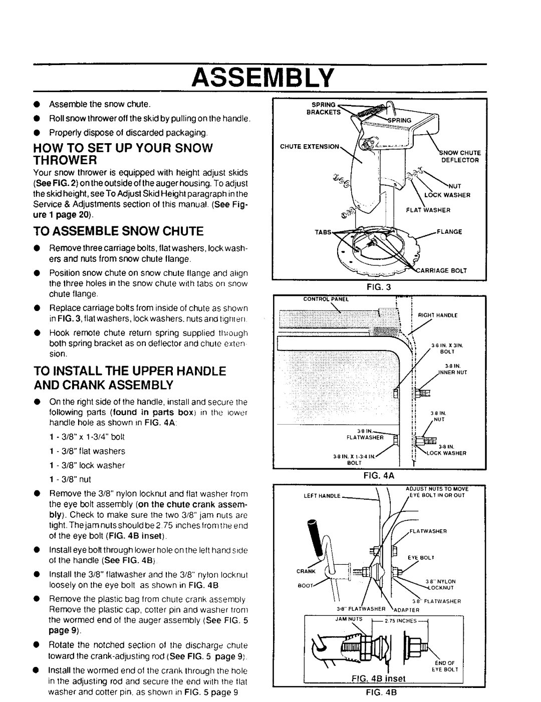
•Remove three carriage bolts, flat washers, lock wash- ers and nuts from snow chute flange.
•Position snow chute on snow chute llange and align the three holes in the snow chute with tabs on snow
chute flange.
•Replace carriage bolts from inside of chute as shown in FIG. 3, flat washers, lock washers, nuts and tight er]
•Hook remote chute return spring supplied through both spring bracket as on deflector and chute exten sion.
TO INSTALL THE UPPER HANDLE AND CRANK ASSEMBLY
•On the right side of the handle, install and secure tile
following pads (found in parts boxl in the lower handle hole as shown in FIG. 4A:
1 - 3/8" x
1 - 3/8" flat washers
1 - 3/8" lock washer
1 - 3/8" nut
Remove the 3/8" nylon Iocknut and flat washer from the eye bolt assembly (on the chute crank assem- bly). Check to make sure the two 3/8" jam nuts are tight. The jam nuts should be 275 inches from _heend of the eye bolt (FIG. 4B inset)
Install eye bolt through lower hole on the left hand side ot the handle (See FIG. 4B)
Install the 3/8" flatwasher and the 3/8" nylon Iocknul loosely on the eye bolt as shown in FIG. 4B
Remove the plastic bag lrom chute crank assembly Remove the plastic cap, cotter pin and washer trom the wormed end of the auger assembly (See FIG. 5 page 9).
Rotate the notched seclion of the discharge chute toward the
Install the wormed end of the crank through the hole in the adjusting rod and secure the end with the tlat washer and cotter pin, as shown in FIG. 5 page 9
BRACKETS
SPRING _
CHUTE EXTENSION | _ #L |
NOW CHUTE
DEFLECTOR
| TABS |
| ., |
| FLANGE |
|
|
| _ARRIAGE |
| BOLT |
|
|
| FIG. 3 |
|
|
| CONTROL | PANEL |
|
| |
" " | _ : : | ." • | " " "_'_" | _ R GHT | HANDLE |
• .... |
|
|
| l |
|
|
|
|
| 3 | 8 IN. X 3IN+ |
|
|
|
| _ | BOLT |
|
|
|
| / | 381N. |
d ,_NNER NUT
381N.
3s8 IN.
FLATWAS_
_LOCK WASHER
3_8 IN. X
BOLT¥
FIG. 4A
ADJUST NUTS TO MOVE
.EYE BOLT IN OR OUT
;LAfWASHER
EYE BOLl
CRANK
38"NYLON
38'FLATWASHER
3sB"ELATWASHERDAPTER
JAM NUTS
\
END OF
EYE BOLT
FIG. 4B inset
FIG. 4B