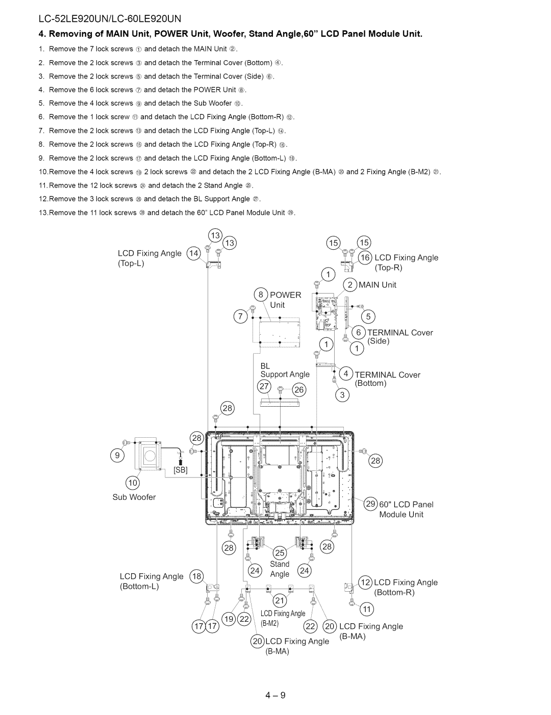
4. Removing of MAIN Unit, POWER Unit, Woofer, Stand Angle,60" LCD Panel Module Unit.
1.Remove the 7 lock screws d) and detach the MAIN Unit _).
2.Remove the 2 lock screws ® and detach the Terminal Cover (Bottom) ®.
3.Remove the 2 lock screws ® and detach the Terminal Cover (Side) ®.
4.Remove the 6 lock screws ® and detach the POWER Unit ®.
5.Remove the 4 lock screws ® and detach the Sub Woofer @.
6.Remove the 1 lock screw @ and detach the LCD Fixing Angle
7.Remove the 2 lock screws @ and detach the LCD Fixing Angle
8.Remove the 2 lock screws @ and detach the LCD Fixing Angle
9.Remove the 2 lock screws @ and detach the LCD Fixing Angle
10.Remove the 4 lock screws @ 2 lock screws @ and detach the 2 LCD Fixing Angle
11.Remove the 12 lock screws @ and detach the 2 Stand Angle ®.
12.Remove the 3 lock screws @ and detach the BL Support Angle ©.
13.Remove the 11 lock screws @ and detach the 60" LCD Panel Module Unit @.
LCD | Fixing Angle | _¢@ | @_1_(_ | LCD Fixing Angle |
| ||||
|
|
)TERMINAL Cover (Bottom)
60" LCD Panel
Module Unit
|
| ,_,1 | :_ |
|
| ||
|
|
| Stand | ,_ |
|
|
|
LCD | Fixing Angle _\ | 2_ | Angle | (2_ |
|
|
|
|
|
|
|
|
| ||
|
|
|
|
|
| ,1_i) LCD Fixing Angle | |
|
|
|
|
| |||
|
|
|
|
|
| ||
|
|
|
|
|
| _] | |
|
|
| LCDFixingAngle | '\ |
|
| |
|
|
| @ | @ | LCD | Fixing Angle | |
|
|
| LCD Fixing Angle | ||||
|
|
|
|
|
| ||