LC-52LE920UN/LC-60LE920UN
11. Factory setting
After completing the factory setting, pull out the AC cord to complete the setting.
CAUTION: Do not turn on the power after completinq the factory settinq. If the power is turned on, confiqure the factory settinq aqain.
Adjustment point | Adjustment conditions |
|
|
|
|
| Adjustment procedure | |
1 Factory setting | Complete the setting by | • Point the cursor to [INDUSTRY | INIT], set | to "ON" using | ||||
| pulling out the AC cord. | the | [ENT] | key. |
|
|
| |
|
| The version confirmation screen appears on the green screen. It is completed when [SUC- | ||||||
|
| CESS] is displayed at the top. |
|
| ||||
|
| (if error occurs, [ERROR] is displayed on the red screen.) | ||||||
|
| • Turn off the AC power. |
|
| ||||
|
| The following items are initialized when configuring the factory setting. | ||||||
|
| 1) | User set value |
|
|
| ||
|
| 2) | Channel | data (broadcasting | frequency, | etc.) | ||
|
| 3) | Password | setting | value |
|
| |
|
| 4) | Operating | time |
|
|
| |
|
| 5) | StandbyCause |
|
|
| ||
|
| 6) | Auto installation | flag |
|
| ||
|
| 7) |
| block setting value |
|
| ||
12. Software version
1.Main microcomputer
2.Monitor microcomputer
3.EDID data (Analog RGB)
4.(Reference: File name in the Technical Department)
For analog RGB Input3: IC509: edid_dsub15_fullhd v6 256.BIN
13.Writing the inch and model name onto EEPROM
Writing method
1.Pull out the AC cord.
2.Copy the application for writing inch/model name (HLI2MA01 .USB) and model/inch file (52LE920.MDL) to the USB memory.
3.Hold down the power button and insert the AC cord.
4.Release the power button after 5 seconds.
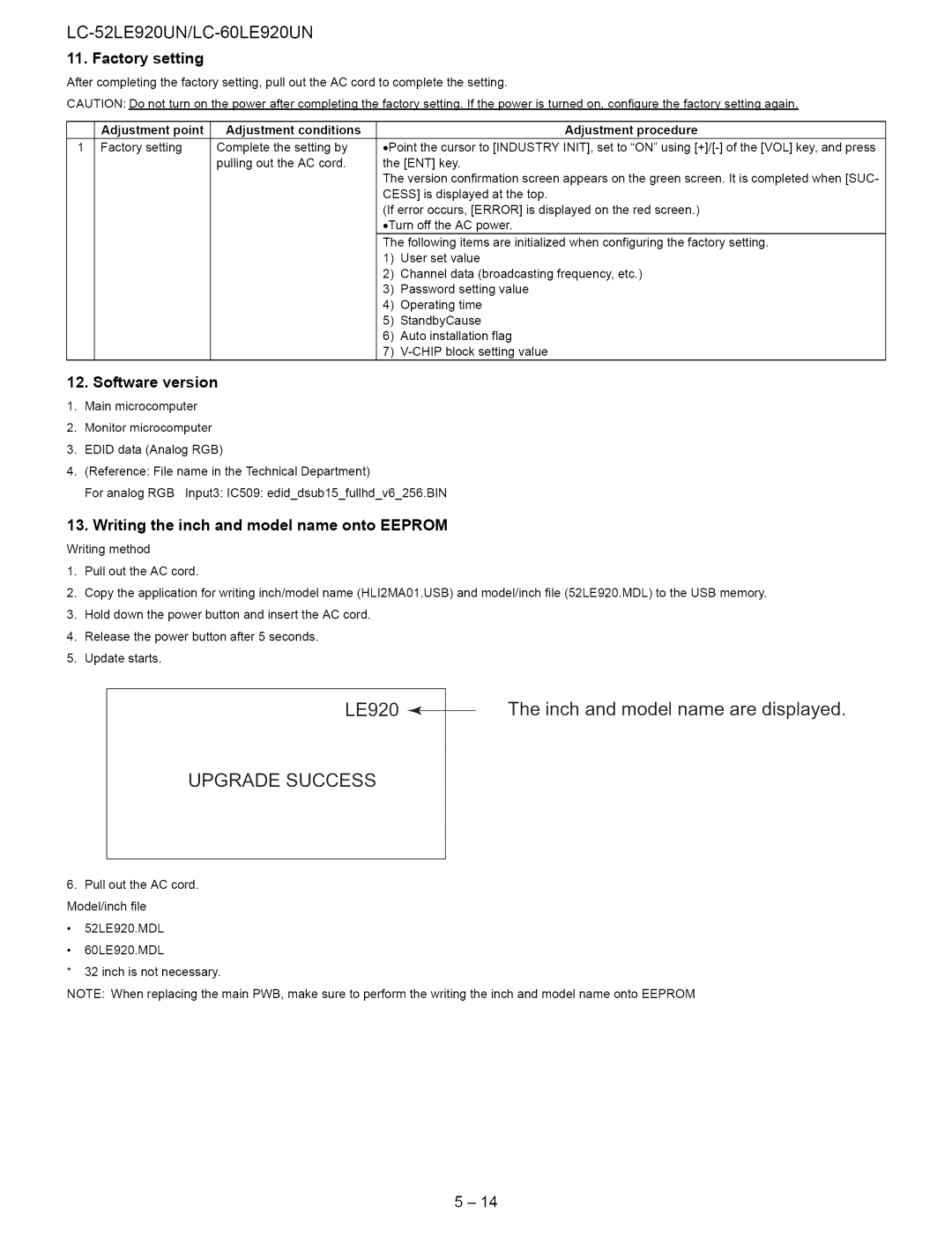
5.Update starts.
LE920 | The inch and model name are displayed. |
UPGRADE SUCCESS
6.Pull out the AC cord. Model/inch file
52LE920.MDL
60LE920.MDL
*32 inch is not necessary.
NOTE: When replacing the main PWB, make sure to perform the writing the inch and model name onto EEPROM