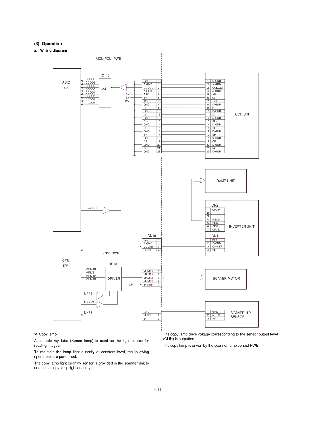
(3) Operation
a. Wiring diagram
ASIC
IC8
MCU(PCU) PWB | ||
| IC112 | |
CCDD0 |
| |
CCDD1 |
| |
CCDD2 | A/D | |
CCDD3 | ||
CCDD4 | 5V | |
CCDD5 | ||
5V | ||
CCDD6 | ||
12V | ||
CCDD7 | ||
| ||
CLCNT |
| |
GND 1
CCDOUT 3
A5V | 5 |
5V | 6 |
12V | 7 |
GND | 8 |
f1 | 9 |
GND | 10 |
f2 | 11 |
GND | 12 |
SH- | 13 |
GND | 14 |
RS | 15 |
GND | 16 |
SP | 17 |
GND | 18 |
CP | 19 |
GND | 20 |
NC | 21 |
GND | 22 |
1
2
3CCDOUT
4
5A5V
65V
712V
8
9f1
10 | CCD UNIT | |
11 | f2 |
12
13SH-
14
15RS
16
17SP
18
19CP
20
21NC
22
| RAMP UNIT |
| |
|
|
|
|
|
|
|
|
| CN2 |
|
|
1 |
|
| |
2 |
|
|
|
3 |
|
|
|
4 | FGND |
|
|
5 | PDA |
|
|
6 | PDK | INVERTER UNIT | |
7 |
|
| |
|
| CN10 |
| |
|
| 24V | 1 | |
|
| 2 | ||
|
| 3 | ||
| (Not used) | 4 | ||
|
|
| ||
CPU | IC13 |
|
| |
IC5 |
|
| ||
|
|
| ||
MRMT0 |
| MRMT0 | 1 | |
MRMT1 |
| |||
| MRMT1 | 2 | ||
MRMT2 |
| |||
DRIVER | MRMT2 | 3 | ||
MRMT3 | ||||
|
| MRMT3 | 4 | |
| 24V | 5 | ||
MRPS1 |
|
|
| |
MRPS2 |
|
|
| |
MHPS |
| GND | 1 | |
|
| MHPS | 2 | |
|
| 5V | 3 |
|
| CN1 |
| 1 | 24V |
| 2 | |
| ||
| 3 | ON/OFF |
| ||
| 4 | PD |
|
SCANER MOTOR
|
|
|
|
| 1 | GND | SCANER H.P |
| 2 | MHPS | |
| SENSOR | ||
| 3 | 5V | |
|
| ||
|
|
|
|
*Copy lamp
A cathode ray tube (Xenon lamp) is used as the light source for reading images.
To maintain the lamp light quantity at constant level, the following operations are performed.
The copy lamp light quantity sensor is provided in the scanner unit to detect the copy lamp light quantity.
The copy lamp drive voltage corresponding to the sensor output level (CLIN) is outputted.
The copy lamp is driven by the scanner lamp control PWB.
1 – 11