(2) Printer mode
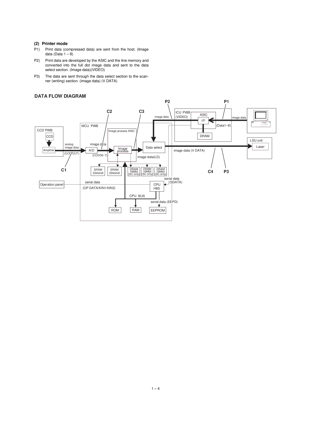
P1) Print data (compressed data) are sent from the host. (Image data (Data 1 – 8)
P2) Print data are developed by the ASIC and the line memory and converted into the full dot image data and sent to the data select section. (Image data)(VIDEO)
P3) The data are sent through the data select section to the scan- ner (writing) section. (image data) (V DATA)
DATA FLOW DIAGRAM
|
|
|
|
|
| P2 |
|
| P1 |
|
| C2 |
| C3 |
| ICU PWB | ASIC |
| |
|
|
|
|
|
| image data | (VIDEO) | image data | |
|
|
|
|
|
| I/F | |||
|
|
|
|
|
|
|
|
| |
| MCU PWB |
|
|
|
|
|
|
| (Data1~8) |
CCD PWB |
| Image process ASIC |
|
|
|
|
| ||
CCD |
|
|
|
|
|
|
| DRAM |
|
|
|
|
|
|
|
|
|
| LSU unit |
analog | image data |
|
|
| Data select |
|
| Laser | |
image data |
| Image |
|
|
|
| |||
Amplifier | A/D |
|
|
|
| image data (V DATA) |
| ||
process |
|
|
|
| |||||
(CCD OUT) | (CCDD0~7) |
|
|
|
|
|
|
| |
|
| image data(LD) |
|
|
| ||||
|
|
|
|
|
|
| |||
C1 | SRAM | SRAM |
| DRAM | DRAM | DRAM |
| C4 | P3 |
| 16Mbit | 16Mbit | 16Mbit |
| |||||
| 32kbitx8 | 32kbitx8 |
|
| |||||
|
|
| (SC only) (SC only) (SC only) |
|
|
| |||
| serial data |
|
|
|
| serial data |
|
| |
Operation panel |
|
|
|
| (SDATA) |
|
| ||
(OP DATA/KIN1/KIN2) |
|
|
| CPU |
|
|
| ||
|
|
|
| H8S |
|
|
| ||
|
|
|
| CPU BUS |
|
|
|
| |
|
|
|
|
| serial data (EEPD) |
|
| ||
|
| ROM |
| RAM | EEPROM |
|
|
| |
1 – 4