MCU PWB BLOCK DIAGRAM
SCANNER MOTOR
MRMT0~3
HOME
POSITION
SENSOR
MHPS_IN
CCD PWB |
| INVERTOR |
| PWB | |
|
| |
|
|
|
f1,f2,
|
|
| CN11 | CN12 | CN14 | CN10 |
|
|
|
|
| |
|
|
|
|
|
|
|
| CN13 | PSIZE_IN | PAPER |
|
|
|
|
| IC13 |
|
| IC112 |
| SIZE |
|
| ||
|
|
|
|
|
|
|
|
|
| SENSOR |
|
|
|
|
|
|
|
|
|
|
|
| VDATA | LASER | |
|
|
|
|
|
|
|
| CN9 |
| LSU PWB | PMCLK | POLYGON |
|
|
| IC5 |
| IC8 |
|
| PMD- | MOTOR | |||
|
|
|
|
|
|
| ||||||
|
|
|
|
|
|
|
| |||||
|
|
| CPU |
| ASIC |
|
|
|
|
|
| |
|
|
| H8S/2350 |
| HG73C025FD |
|
|
| PEMP_IN | PAPER | ||
|
|
|
|
|
|
|
|
|
| EMPTY | ||
|
|
|
|
|
|
|
|
|
|
|
| SENSOR |
PAPER |
| CN7 |
|
|
|
|
|
|
|
| ||
EXIT | PSIZE_IN |
|
|
|
|
| CN8 |
|
| |||
SENSOR |
|
|
|
|
|
|
|
| ICU PWB | |||
|
|
|
|
|
|
| ||||||
|
|
|
|
|
|
|
|
| RESET,DREADY- |
|
| |
|
|
|
|
|
|
|
|
|
|
| ||
|
|
|
|
|
|
|
|
| SCLK,SYNC |
|
| |
THERMISTOR | RTH_IN | CN2 |
|
|
|
|
|
|
|
|
|
|
|
| CN1 |
| CN4 |
| CN5 |
| CN6 |
|
|
|
|
|
| OPCLK,OPLATCH | OPPSW |
|
| PIN_IN- | TS_IN |
|
|
|
| |
|
| VFMOUT | MCON,HL,TC/BIASON |
|
|
|
| |||||
|
| FW |
|
|
|
| ||||||
|
| OPDATA,SELIN1,2,3OPKIN1,2 |
|
| PUS,PR,PWMSIN |
|
|
|
|
| ||
|
|
|
|
|
|
|
|
|
|
|
| |
|
| OPERATION PANEL | FAN MOTOR |
| HIGH VOLTAGE PWB | TONER |
|
|
|
| ||
|
|
| SENSOR |
|
|
|
| |||||
|
|
|
|
|
|
|
|
|
|
|
| |
ICU PWB
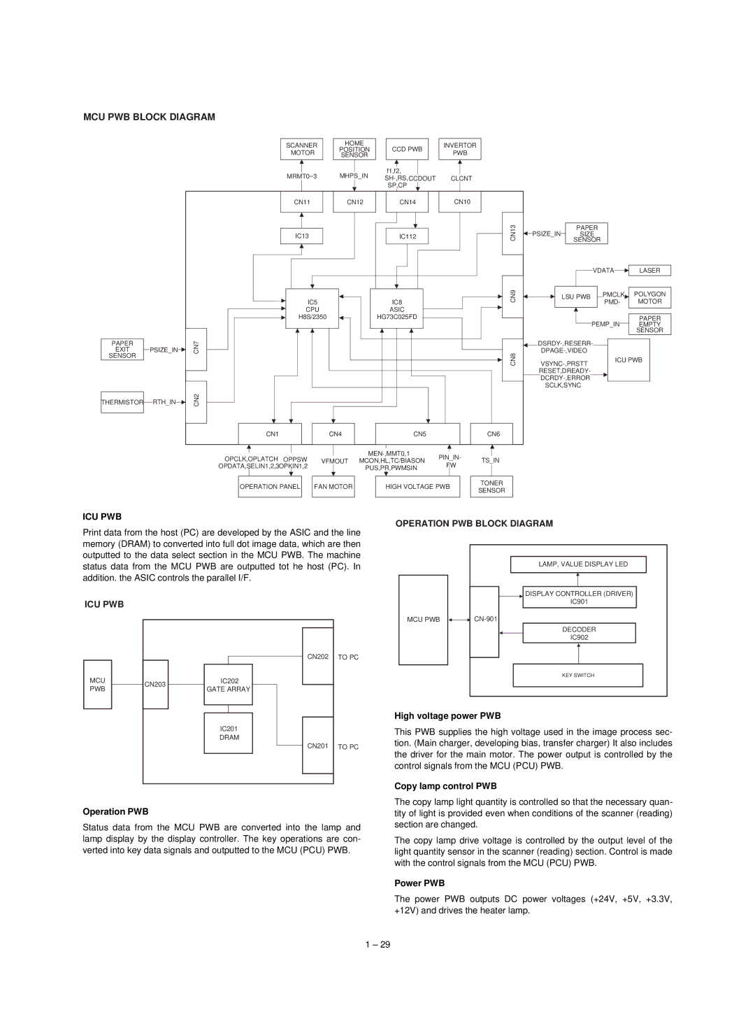
Print data from the host (PC) are developed by the ASIC and the line memory (DRAM) to converted into full dot image data, which are then outputted to the data select section in the MCU PWB. The machine status data from the MCU PWB are outputted tot he host (PC). In addition. the ASIC controls the parallel I/F.
ICU PWB
OPERATION PWB BLOCK DIAGRAM | |
| LAMP, VALUE DISPLAY LED |
| DISPLAY CONTROLLER (DRIVER) |
| IC901 |
MCU PWB | |
| DECODER |
| IC902 |
MCU PWB
CN203
IC202
GATE ARRAY
IC201
DRAM
CN202
CN201
TO PC
TO PC
KEY SWITCH |
High voltage power PWB
This PWB supplies the high voltage used in the image process sec- tion. (Main charger, developing bias, transfer charger) It also includes the driver for the main motor. The power output is controlled by the control signals from the MCU (PCU) PWB.
Copy lamp control PWB
Operation PWB
Status data from the MCU PWB are converted into the lamp and lamp display by the display controller. The key operations are con- verted into key data signals and outputted to the MCU (PCU) PWB.
The copy lamp light quantity is controlled so that the necessary quan- tity of light is provided even when conditions of the scanner (reading) section are changed.
The copy lamp drive voltage is controlled by the output level of the light quantity sensor in the scanner (reading) section. Control is made with the control signals from the MCU (PCU) PWB.
Power PWB
The power PWB outputs DC power voltages (+24V, +5V, +3.3V, +12V) and drives the heater lamp.
1 – 29
