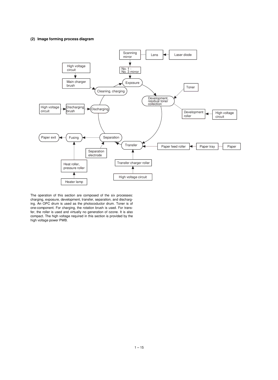
(2) Image forming process diagram
High voltage circuit
Main charger brush
Scanning mirror
No. 1 -
No. 3 mirror
Exposure
Cleaning, charging
Lens |
| Laser diode |
|
|
|
Toner
Development, residual toner collection
High voltage circuit
Paper exit
Discharging | Discharging | |
brush | ||
|
FusingSeparation
Development roller
High voltage circuit
Transfer
Separation electrode
Paper feed roller |
| Paper tray |
| Paper |
|
|
|
|
|
Heat roller, |
|
| Transfer charger roller |
|
|
|
| ||
pressure roller |
|
|
| |
|
|
|
|
|
|
|
|
|
|
|
|
| High voltage circuit |
|
Heater lamp |
|
|
|
|
|
|
| ||
|
|
|
|
|
The operation of this section are composed of the six processes: charging, exposure, development, transfer, separation, and discharg- ing. An OPC drum is used as the photocoductor drum. Toner is of
1 – 15
