(3) Operation
a. Wiring diagram
CPU
(IC5)
ASIC (IC202)
MCU(PCU) PWB | POWER SUPPLY PWB |
| Fusing section | |
| AC POWER IN |
| Temperature fuse | |
| CN603 | |||
| (132 C) | |||
HLON | HLON- | HLL | ||
| ||||
| 1/3 |
| ||
Gate |
|
| Temperature fuse | |
|
|
| (187 C) | |
|
|
|
| Heater |
|
|
|
| lamp |
RTH |
|
|
| CN603 |
|
|
|
| |
| COMP |
| PR | 2/4 HLN |
|
|
| ||
|
|
|
| |
AMP | CN2 |
|
| Thermistor |
| GND | 1 |
| RTH |
| RTHN 2 |
| ||
PR |
|
| ||
|
|
|
| |
|
|
| +24V | CN801 |
DRIVER |
| 1 | +24V | |
| High voltage power PWB | 2 | NC | |
|
|
| 3 | +24VS |
b. Operation | Heat roller: | The heat roller is made of aluminum |
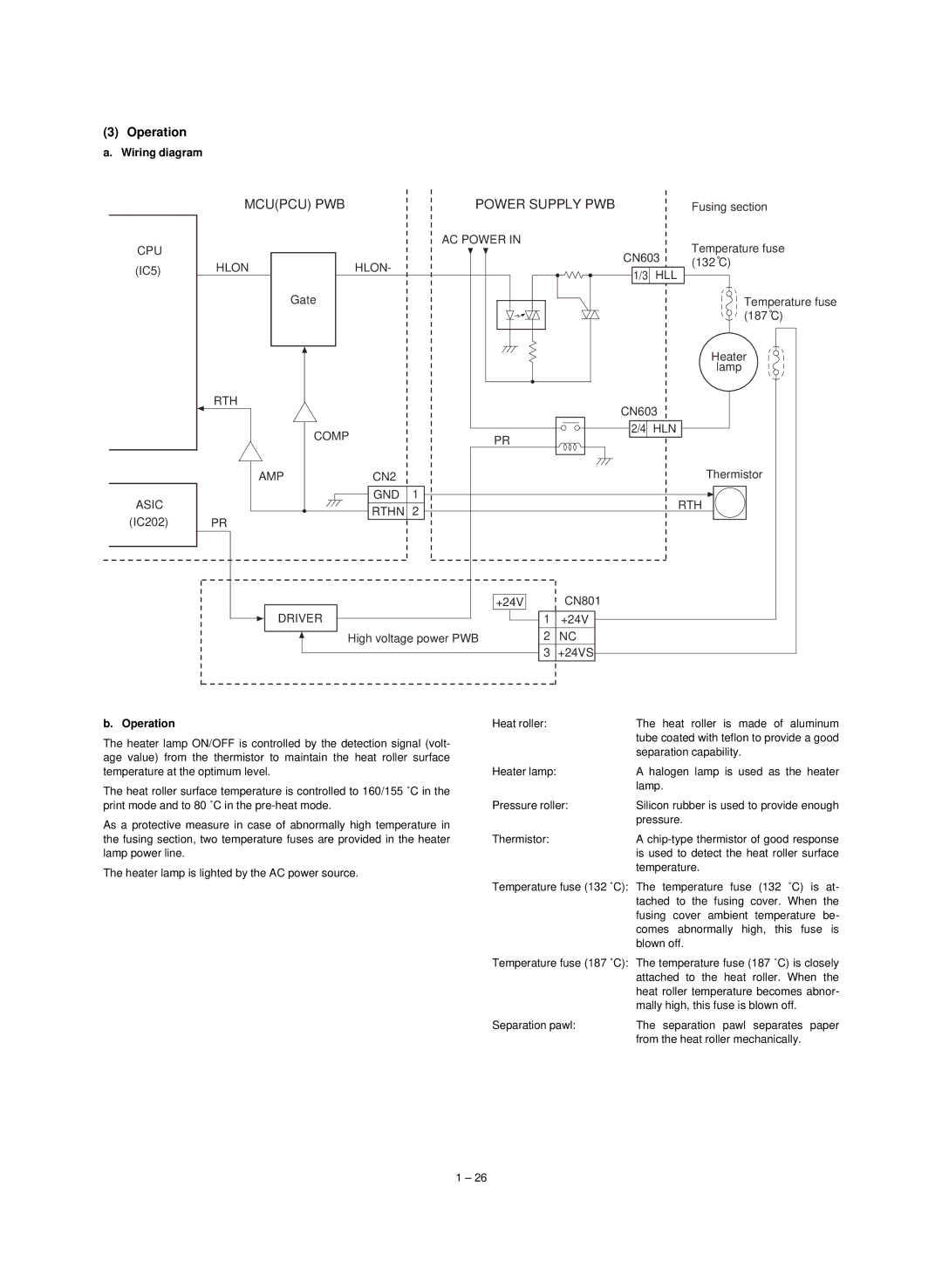
The heater lamp ON/OFF is controlled by the detection signal (volt- |
| tube coated with teflon to provide a good |
| separation capability. | |
age value) from the thermistor to maintain the heat roller surface |
| |
|
| |
temperature at the optimum level. | Heater lamp: | A halogen lamp is used as the heater |
The heat roller surface temperature is controlled to 160/155 ˚C in the |
| lamp. |
|
| |
print mode and to 80 ˚C in the | Pressure roller: | Silicon rubber is used to provide enough |
As a protective measure in case of abnormally high temperature in |
| pressure. |
|
| |
the fusing section, two temperature fuses are provided in the heater | Thermistor: | A |
lamp power line. |
| is used to detect the heat roller surface |
The heater lamp is lighted by the AC power source. |
| temperature. |
|
| |
| Temperature fuse (132 ˚C): The temperature fuse (132 ˚C) is at- | |
|
| tached to the fusing cover. When the |
|
| fusing cover ambient temperature be- |
|
| comes abnormally high, this fuse is |
|
| blown off. |
| Temperature fuse (187 ˚C): The temperature fuse (187 ˚C) is closely | |
|
| attached to the heat roller. When the |
|
| heat roller temperature becomes abnor- |
|
| mally high, this fuse is blown off. |
| Separation pawl: | The separation pawl separates paper |
|
| from the heat roller mechanically. |
1 – 26
