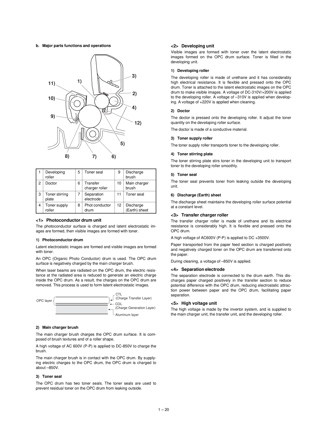
b. Major parts functions and operations
|
| 1) |
|
| 3) |
| 11) |
|
|
| |
|
|
|
|
| |
| 10) |
|
|
| 2) |
|
|
|
|
| |
|
|
|
|
| 4) |
| 9) |
|
|
|
|
|
|
|
|
| 12) |
|
|
|
| 5) |
|
| 8) |
| 7) | 6) |
|
1 | Developing | 5 | Toner seal | 9 | Discharge |
| roller |
|
|
| brush |
2 | Doctor | 6 | Transfer | 10 | Main charger |
|
|
| charger roller |
| brush |
3 | Toner stirring | 7 | Separation | 11 | Toner seal |
| plate |
| electrode |
|
|
4 | Toner supply | 8 | Phot conductor | 12 | Discharge |
| roller |
| drum |
| (Earth) sheet |
<1> Photoconductor drum unit
The photoconductor surface is charged and latent electrostatic im- ages are formed, then visible images are formed with toner.
1) Photoconductor drum
Latent electrostatic images are formed and visible images are formed with toner.
An OPC (Organic Photo Conductor) drum is used. The OPC drum surface is negatively charged by the main charger brush.
When laser beams are radiated on the OPC drum, the electric resis- tance at the radiated area is reduced to generate an electric charge inside the OPC drum. As a result, the charges on the OPC drum are removed. This process is used to form latent electrostatic images.
CTL
(Charge Transfer Layer)
OPC layer
CGL
(Charge Generation Layer)
Aluminum layer
2) Main charger brush
The main charger brush charges the OPC drum surface. It is com- posed of brush textures and of a roller shape.
A high voltage of AC 600V
The main charger brush is in contact with the OPC drum. By supply- ing electric charges to the OPC drum, the OPC drum is charged to about
3) Toner seal
The OPC drum has two toner seals. The toner seals are used to prevent residual toner on the OPC drum from leaking outside.
<2> Developing unit
Visible images are formed with toner over the latent electrostatic images formed on the OPC drum surface. Toner is filled in the developing unit.
1) Developing roller
The developing roller is made of urethane and it has considerably high electrical resistance. It is flexible and pressed onto the OPC drum. Toner is attached to the latent electrostatic images on the OPC drum to make visible images. A voltage of
2) Doctor
The doctor is pressed onto the developing roller. It adjust the toner quantity on the developing roller surface.
The doctor is made of a conductive material.
3) Toner supply roller
The toner supply roller transports toner to the developing roller.
4) Toner stirring plate
The toner stirring plate stirs toner in the developing unit to transport toner to the developing roller smoothly.
5) Toner seal
The toner seal prevents toner from leaking outside the developing unit.
6) Discharge (Earth) sheet
The discharge sheet maintains the developing roller surface potential at a constant level.
<3> Transfer charger roller
The transfer charger roller is made of urethane and its electrical resistance is considerably high. It is flexible and pressed onto the OPC drum.
A high voltage of AC600V
Paper transported from the paper feed section is charged positively and negatively charged toner on the OPC drum are transferred onto the paper.
During cleaning, a voltage of
<4> Separation electrode
The separation electrode is connected to the drum earth. This dis- charges paper charged positively in the transfer section to reduce potential difference with the OPC drum, reducing electrostatic attrac- tion power between paper and the OPC drum, facilitating paper separation.
<5> High voltage unit
The high voltage is made by the invertor system, and is supplied to the main charger unit, the transfer unit, and the developing roller.
1 – 20