Specifications
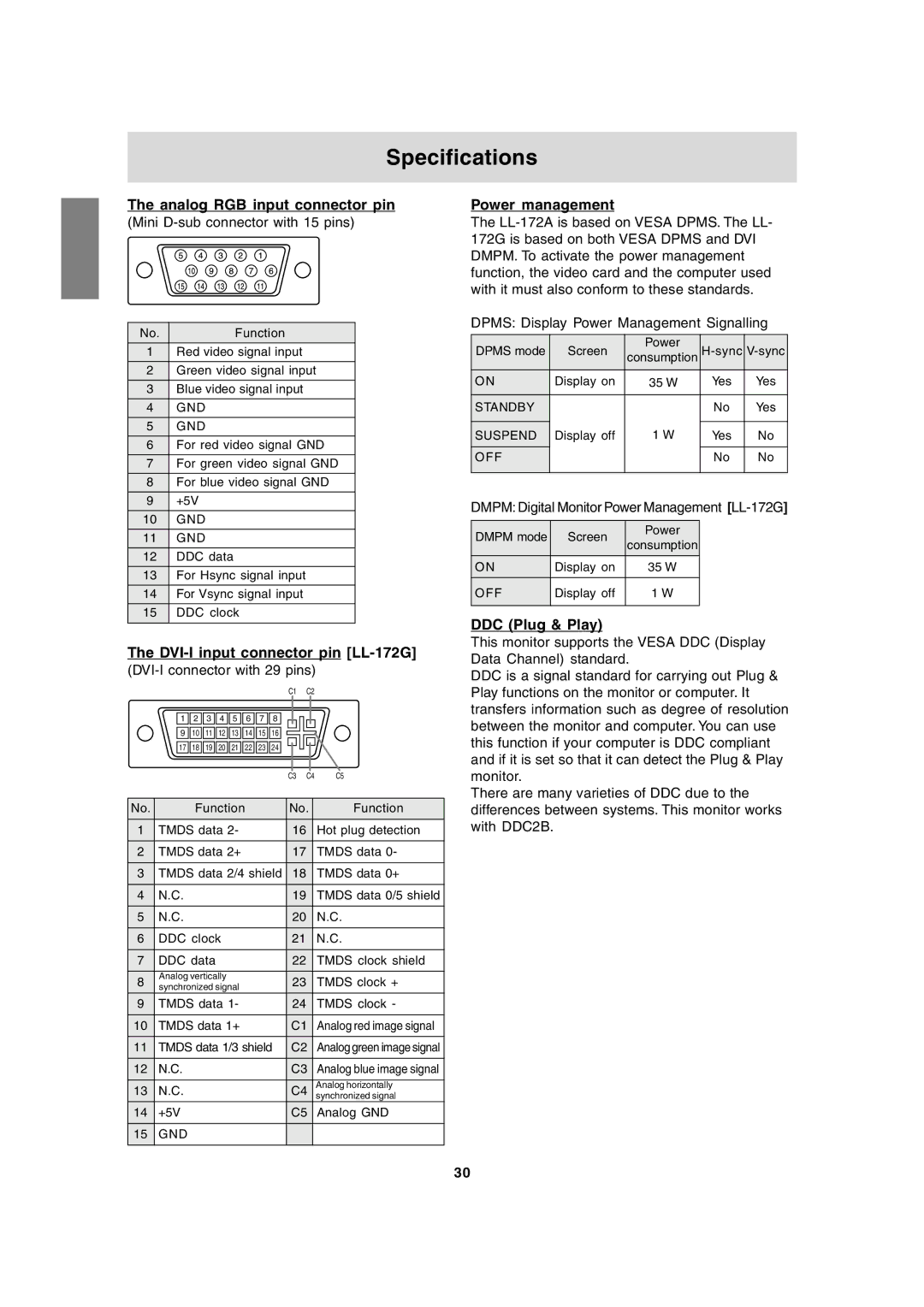
The analog RGB input connector pin
(Mini D-sub connector with 15 pins)
No. | Function |
1 | Red video signal input |
2 | Green video signal input |
3 | Blue video signal input |
4 | GND |
5 | GND |
6 | For red video signal GND |
7 | For green video signal GND |
8 | For blue video signal GND |
9 | +5V |
10 | GND |
11 | GND |
12 | DDC data |
13 | For Hsync signal input |
14 | For Vsync signal input |
15 | DDC clock |
|
|
The DVI-I input connector pin [LL-172G]
(DVI-I connector with 29 pins)
C1 C2
| 1 | 2 | 3 | 4 | 5 | 6 | 7 | 8 |
|
|
|
|
|
|
|
|
|
|
|
|
| ||||||||
| 9 | 10 | 11 | 12 | 13 | 14 | 15 | 16 |
|
|
|
|
|
|
|
|
|
|
|
|
| ||||||||
|
|
|
|
|
|
| ||||||||
| 17 | 18 | 19 | 20 | 21 | 22 | 23 | 24 |
|
|
|
|
| C5 |
|
|
|
|
|
| |||||||||
|
|
|
|
|
|
|
|
|
|
|
| |||
|
|
|
|
|
|
|
|
| C3 | C4 | ||||
|
|
|
|
|
|
|
|
| ||||||
No. |
| Function |
|
|
|
| No. | Function | ||||||
1 | TMDS data 2- |
|
|
| 16 |
| Hot plug detection | |||||||
2 | TMDS data 2+ |
|
|
| 17 |
| TMDS data 0- | |||||||
3 | TMDS data 2/4 shield | 18 |
| TMDS data 0+ | ||||||||||
4 | N.C. |
|
|
|
|
|
|
| 19 |
| TMDS data 0/5 shield | |||
5 | N.C. |
|
|
|
|
|
|
| 20 |
| N.C. | |||
6 | DDC clock |
|
|
|
| 21 |
| N.C. | ||||||
7 | DDC data |
|
|
|
|
| 22 |
| TMDS clock shield | |||||
8 | Analog vertically |
|
|
|
| 23 |
| TMDS clock + | ||||||
synchronized signal |
|
|
|
| ||||||||||
9 | TMDS data 1- |
|
|
| 24 |
| TMDS clock - | |||||||
10 | TMDS data 1+ |
|
|
|
| C1 | Analog red image signal | |||||||
11 | TMDS data 1/3 shield |
| C2 | Analog green image signal | ||||||||||
12 | N.C. |
|
|
|
|
|
|
|
| C3 | Analog blue image signal | |||
13 | N.C. |
|
|
|
|
|
|
|
| C4 | Analog horizontally | |||
|
|
|
|
|
|
|
| synchronized signal | ||||||
14 | +5V |
|
|
|
|
|
|
|
| C5 | Analog GND | |||
15 | GND |
|
|
|
|
|
|
|
|
|
|
|
|
|
|
|
|
|
|
|
|
|
|
|
|
|
|
|
|
Power management
The
DPMS: Display Power Management Signalling
DPMS mode | Screen | Power | ||
consumption | ||||
|
|
|
|
|
ON | Display on | 35 W | Yes | Yes |
|
|
|
|
|
STANDBY |
|
| No | Yes |
|
| 1 W |
|
|
SUSPEND | Display off | Yes | No | |
OFF |
|
| No | No |
|
|
|
|
|
DMPM: Digital Monitor Power Management
DMPM mode | Screen | Power | |
consumption | |||
|
| ||
ON | Display on | 35 W | |
OFF | Display off | 1 W | |
|
|
|
DDC (Plug & Play)
This monitor supports the VESA DDC (Display Data Channel) standard.
DDC is a signal standard for carrying out Plug & Play functions on the monitor or computer. It transfers information such as degree of resolution between the monitor and computer. You can use this function if your computer is DDC compliant and if it is set so that it can detect the Plug & Play monitor.
There are many varieties of DDC due to the differences between systems. This monitor works with DDC2B.
30
