START VIEW
(7) |
Module Cover |
(2) |
Module Assy |
(8) Captive Screw |
(1) Captive Screws |
(6) |
Serial Data Cable - Not used with
FINISH VIEW
(7) |
Module Cover |
(4) |
Modem Card |
(2) |
Module Assy |
(8) Captive Screw |
(5) Cover Mount |
Standoff |
(3) Threaded |
Standoff |
(6) |
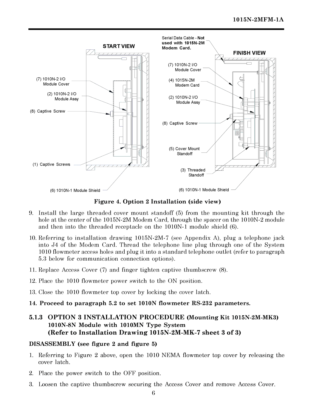
Figure 4. Option 2 Installation (side view)
9.Install the large threaded cover mount standoff (5) from the mounting kit through the hole at the center of the 1015N-2M Modem Card, through the spacer on the 1010N-2 module and then into the threaded receptacle on the 1010N-1 module shield (6).
10.Referring to installation drawing 1015N-2M-7 (see Appendix A), plug a telephone jack into J4 of the Modem Card. Thread the telephone line plug through one of the System 1010 flowmeter access holes and plug it into a standard telephone outlet (refer to paragraph
5.3below for communication connection options).
11.Replace Access Cover (7) and finger tighten captive thumbscrew (8).
12.Place the 1010 flowmeter power switch to the ON position.
13.Close the 1010 flowmeter top cover by locking the cover latch.
14.Proceed to paragraph 5.2 to set 1010N flowmeter RS-232 parameters.
5.1.3OPTION 3 INSTALLATION PROCEDURE (Mounting Kit 1015N-2M-MK3) 1010N-8N Module with 1010MN Type System
(Refer to Installation Drawing 1015N-2M-MK-7 sheet 3 of 3)
DISASSEMBLY (see figure 2 and figure 5)
1.Referring to Figure 2 above, open the 1010 NEMA flowmeter top cover by releasing the cover latch.
2.Place the power switch to the OFF position.
3.Loosen the captive thumbscrew securing the Access Cover and remove Access Cover.
6