1015N-2MFM-1A
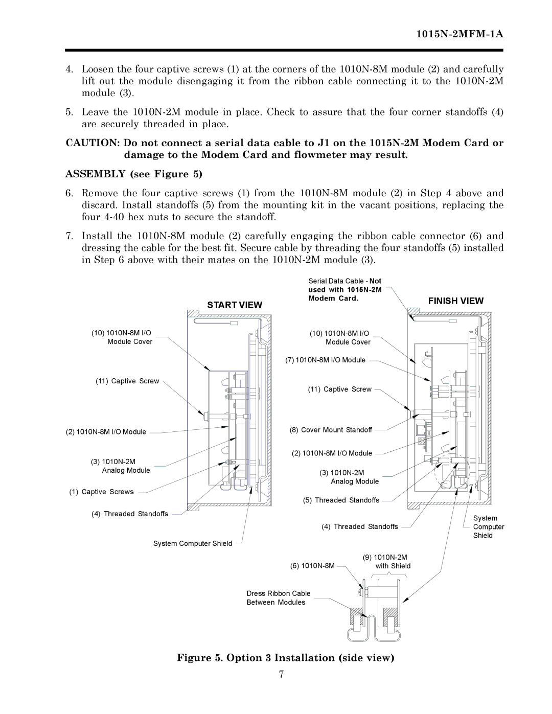
4.Loosen the four captive screws (1) at the corners of the 1010N-8M module (2) and carefully lift out the module disengaging it from the ribbon cable connecting it to the 1010N-2M module (3).
5.Leave the 1010N-2M module in place. Check to assure that the four corner standoffs (4) are securely threaded in place.
CAUTION: Do not connect a serial data cable to J1 on the 1015N-2M Modem Card or damage to the Modem Card and flowmeter may result.
ASSEMBLY (see Figure 5)
6.Remove the four captive screws (1) from the 1010N-8M module (2) in Step 4 above and discard. Install standoffs (5) from the mounting kit in the vacant positions, replacing the four 4-40 hex nuts to secure the standoff.
7.Install the 1010N-8M module (2) carefully engaging the ribbon cable connector (6) and dressing the cable for the best fit. Secure cable by threading the four standoffs (5) installed in Step 6 above with their mates on the 1010N-2M module (3).
START VIEW
(10) 1010N-8M I/O |
Module Cover |
(11) Captive Screw |
(2) 1010N-8M I/O Module |
(3) 1010N-2M |
Analog Module |
(1) Captive Screws |
(4) Threaded Standoffs
System Computer Shield
Serial Data Cable - Not | |
used with 1015N-2M | |
Modem Card. | FINISH VIEW |
|
(10) 1010N-8M I/O | | |
Module Cover | | |
(7) 1010N-8M I/O Module | | |
(11) Captive Screw | | |
(8) Cover Mount Standoff | | |
(2) 1010N-8M I/O Module | | |
(3) 1010N-2M | | |
Analog Module | |
(5) Threaded Standoffs | |
| | System |
(4) Threaded Standoffs | Computer |
| | Shield |
(9) 1010N-2M | |
(6) 1010N-8M | with Shield | |
Dress Ribbon Cable |
Between Modules |
Figure 5. Option 3 Installation (side view)