© Siemens AG 2011
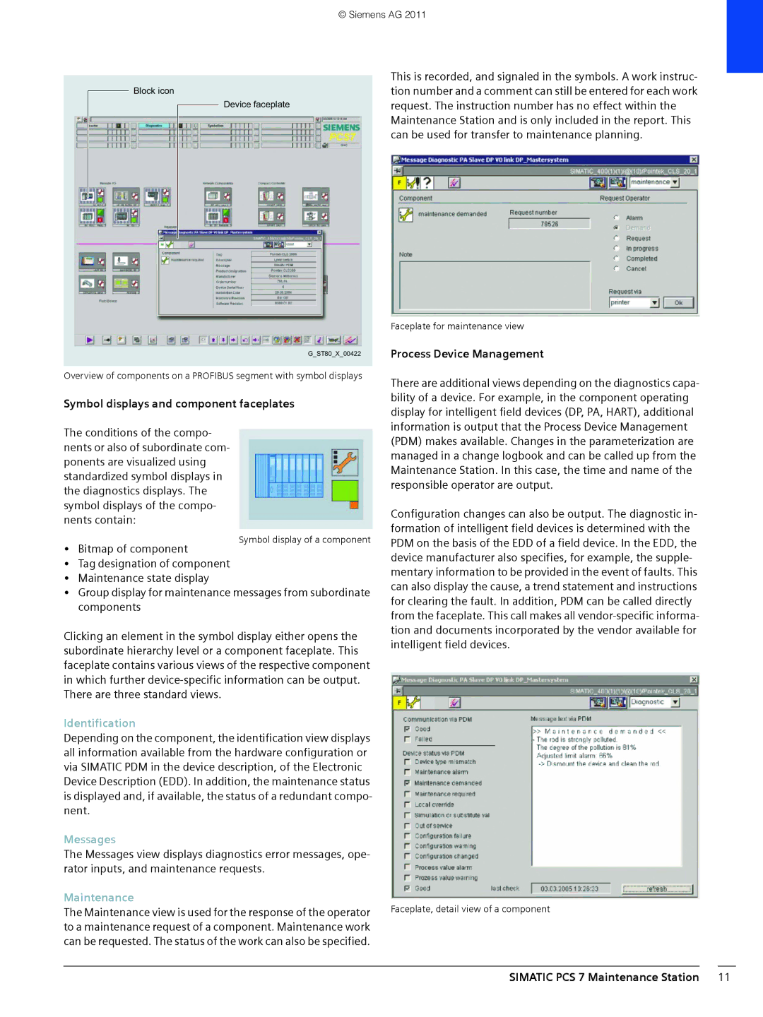
Block icon
Device faceplate
G_ST80_X_00422
Overview of components on a PROFIBUS segment with symbol displays
Symbol displays and component faceplates
The conditions of the compo- nents or also of subordinate com- ponents are visualized using standardized symbol displays in the diagnostics displays. The symbol displays of the compo- nents contain:
• Bitmap of component
• Tag designation of component
• Maintenance state display
• Group display for maintenance messages from subordinate components
Clicking an element in the symbol display either opens the subordinate hierarchy level or a component faceplate. This faceplate contains various views of the respective component in which further
Identification
Depending on the component, the identification view displays all information available from the hardware configuration or via SIMATIC PDM in the device description, of the Electronic Device Description (EDD). In addition, the maintenance status is displayed and, if available, the status of a redundant compo- nent.
Messages
The Messages view displays diagnostics error messages, ope- rator inputs, and maintenance requests.
Maintenance
The Maintenance view is used for the response of the operator to a maintenance request of a component. Maintenance work can be requested. The status of the work can also be specified.
This is recorded, and signaled in the symbols. A work instruc- tion number and a comment can still be entered for each work request. The instruction number has no effect within the Maintenance Station and is only included in the report. This can be used for transfer to maintenance planning.
Faceplate for maintenance view
Process Device Management
There are additional views depending on the diagnostics capa- bility of a device. For example, in the component operating display for intelligent field devices (DP, PA, HART), additional information is output that the Process Device Management (PDM) makes available. Changes in the parameterization are managed in a change logbook and can be called up from the Maintenance Station. In this case, the time and name of the responsible operator are output.
Configuration changes can also be output. The diagnostic in- formation of intelligent field devices is determined with the PDM on the basis of the EDD of a field device. In the EDD, the device manufacturer also specifies, for example, the supple- mentary information to be provided in the event of faults. This can also display the cause, a trend statement and instructions for clearing the fault. In addition, PDM can be called directly from the faceplate. This call makes all
Faceplate, detail view of a component