CONNECTOR PINOUT
This section provides the pinout of the
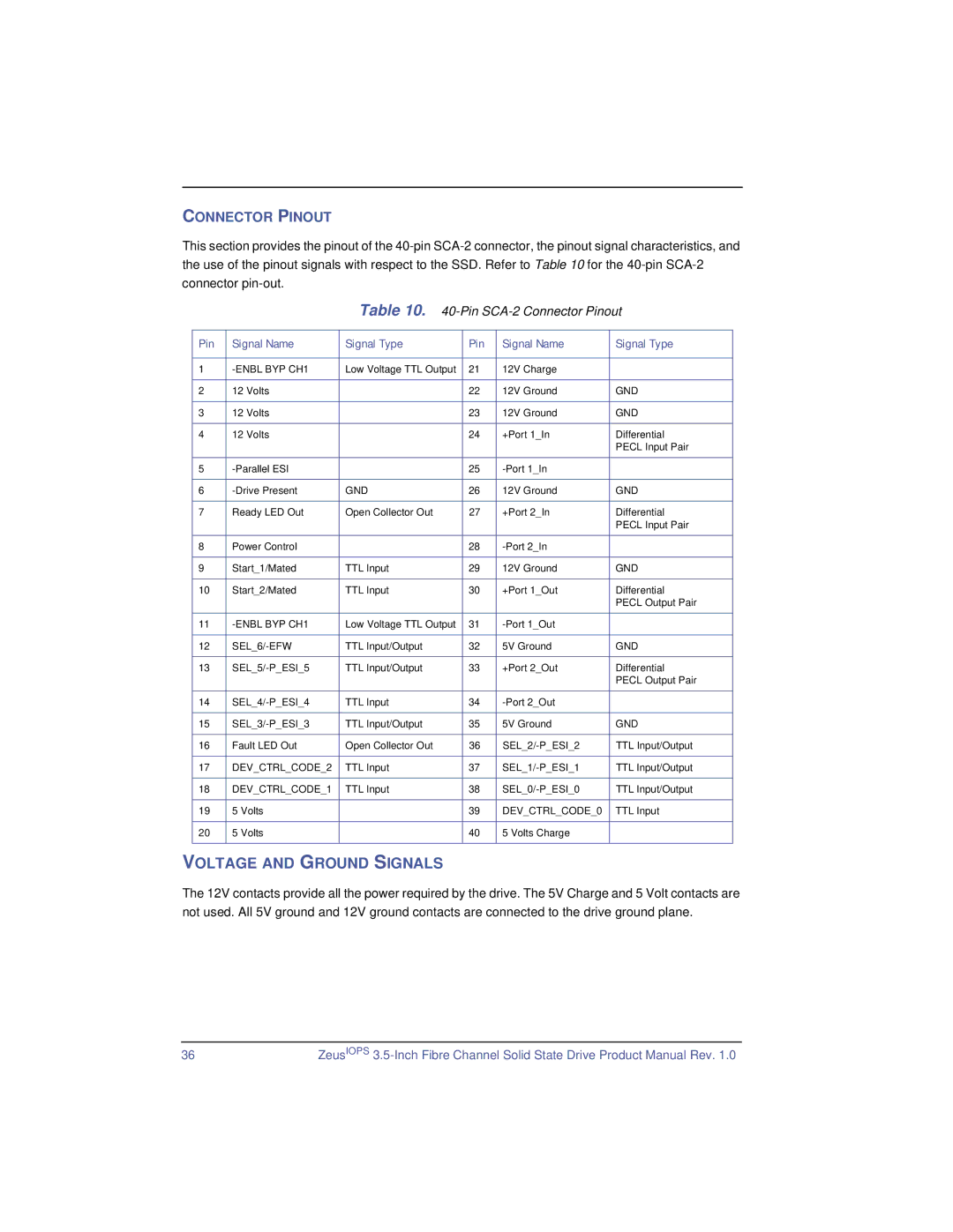
Table 10. 40-Pin SCA-2 Connector Pinout
Pin | Signal Name | Signal Type | Pin | Signal Name | Signal Type |
|
|
|
|
|
|
1 | Low Voltage TTL Output | 21 | 12V Charge |
| |
|
|
|
|
|
|
2 | 12 Volts |
| 22 | 12V Ground | GND |
|
|
|
|
|
|
3 | 12 Volts |
| 23 | 12V Ground | GND |
|
|
|
|
|
|
4 | 12 Volts |
| 24 | +Port 1_In | Differential |
|
|
|
|
| PECL Input Pair |
5 |
| 25 |
| ||
|
|
|
|
|
|
6 | GND | 26 | 12V Ground | GND | |
|
|
|
|
|
|
7 | Ready LED Out | Open Collector Out | 27 | +Port 2_In | Differential |
|
|
|
|
| PECL Input Pair |
8 | Power Control |
| 28 |
| |
|
|
|
|
|
|
9 | Start_1/Mated | TTL Input | 29 | 12V Ground | GND |
|
|
|
|
|
|
10 | Start_2/Mated | TTL Input | 30 | +Port 1_Out | Differential |
|
|
|
|
| PECL Output Pair |
11 | Low Voltage TTL Output | 31 |
| ||
|
|
|
|
|
|
12 | TTL Input/Output | 32 | 5V Ground | GND | |
|
|
|
|
|
|
13 | TTL Input/Output | 33 | +Port 2_Out | Differential | |
|
|
|
|
| PECL Output Pair |
14 | TTL Input | 34 |
| ||
|
|
|
|
|
|
15 | TTL Input/Output | 35 | 5V Ground | GND | |
|
|
|
|
|
|
16 | Fault LED Out | Open Collector Out | 36 | TTL Input/Output | |
|
|
|
|
|
|
17 | DEV_CTRL_CODE_2 | TTL Input | 37 | TTL Input/Output | |
|
|
|
|
|
|
18 | DEV_CTRL_CODE_1 | TTL Input | 38 | TTL Input/Output | |
|
|
|
|
|
|
19 | 5 Volts |
| 39 | DEV_CTRL_CODE_0 | TTL Input |
|
|
|
|
|
|
20 | 5 Volts |
| 40 | 5 Volts Charge |
|
|
|
|
|
|
|
VOLTAGE AND GROUND SIGNALS
The 12V contacts provide all the power required by the drive. The 5V Charge and 5 Volt contacts are not used. All 5V ground and 12V ground contacts are connected to the drive ground plane.
36 | ZeusIOPS |