Assembly
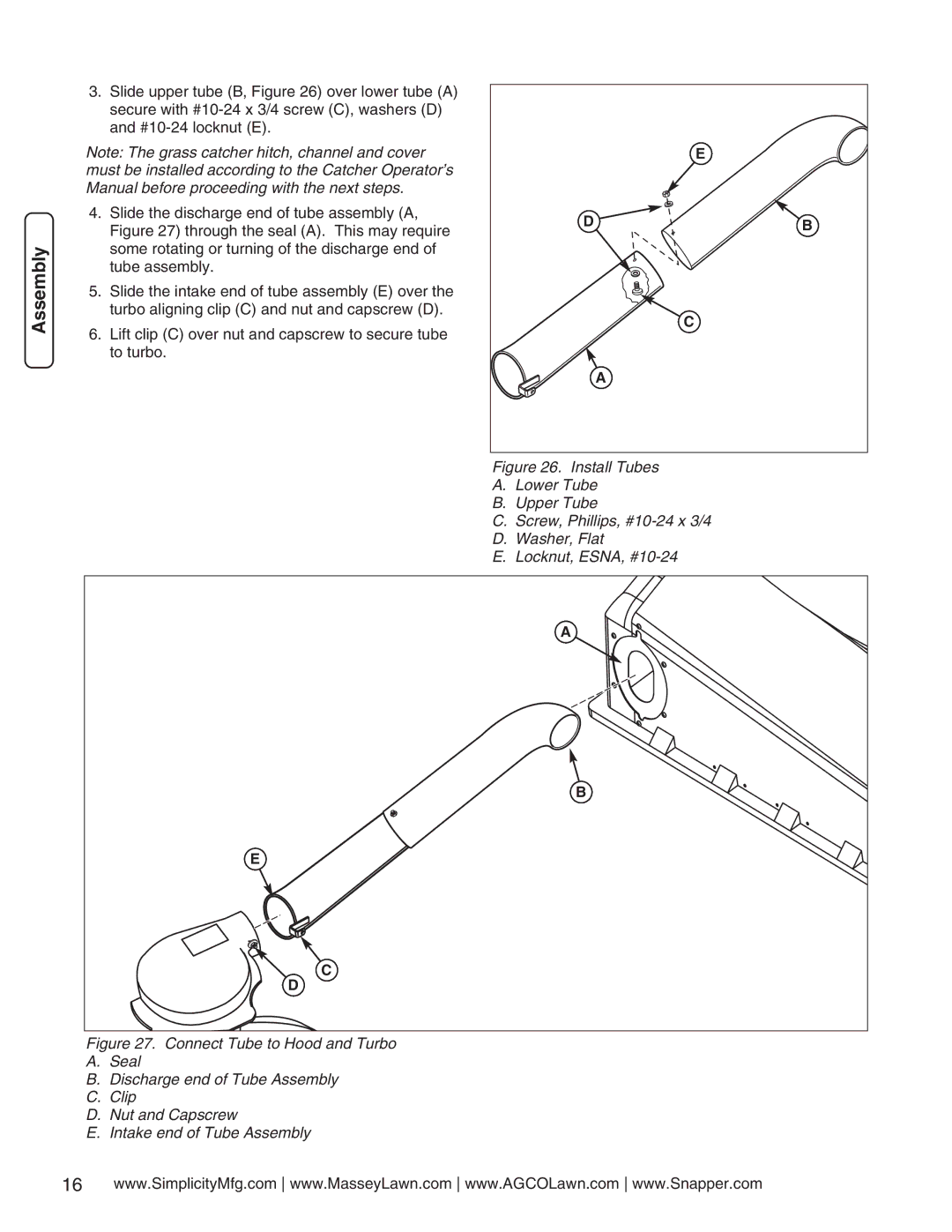
3.Slide upper tube (B, Figure 26) over lower tube (A) secure with
Note: The grass catcher hitch, channel and cover must be installed according to the Catcher Operator’s Manual before proceeding with the next steps.
4.Slide the discharge end of tube assembly (A, Figure 27) through the seal (A). This may require some rotating or turning of the discharge end of tube assembly.
5.Slide the intake end of tube assembly (E) over the turbo aligning clip (C) and nut and capscrew (D).
6.Lift clip (C) over nut and capscrew to secure tube to turbo.
| E |
D | B |
| C |
| A |
Figure 26. Install Tubes
A. Lower Tube
B. Upper Tube
C. Screw, Phillips, #10-24 x 3/4
D. Washer, Flat
E. Locknut, ESNA, #10-24
A |
B |
E |
C |
D |
Figure 27. Connect Tube to Hood and Turbo
A.Seal
B.Discharge end of Tube Assembly
C.Clip
D.Nut and Capscrew
E.Intake end of Tube Assembly
16www.SimplicityMfg.com www.MasseyLawn.com www.AGCOLawn.com www.Snapper.com