| Assembly and adjustments |
| |
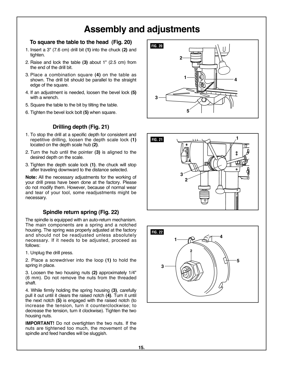
1. | To square the table to the head (Fig. 20) | FIG. 20 |
|
Insert a 3" (7.6 cm) drill bit (1) into the chuck (2) and |
|
| |
| tighten. | 2 |
|
2. Raise and lock the table (3) about 1" (2.5 cm) from |
| ||
| the end of the drill bit. |
|
|
3. Place a combination square (4) on the table as | 1 | 4 | |
| shown. The drill bit should be parallel to the straight | ||
4. | edge of the square. |
|
|
If an adjustment is needed, loosen the bevel lock (5) | 3 |
| |
5. | with a wrench. |
| |
Square the table to the bit by tilting the table. | 5 |
| |
6. | Tighten the bevel lock bolt (5) when square. |
| |
Drilling depth (Fig. 21) |
|
|
|
|
|
1. To stop the drill at a specific depth for consistent and |
|
|
|
| 1 |
repetitive drilling, loosen the depth scale lock (1) | FIG. 21 |
|
|
| |
located on the depth scale hub (2). |
|
|
|
|
|
2. Turn the hub until the pointer (3) is aligned to the |
|
|
|
|
|
desired depth on the scale. |
|
|
|
|
|
3. Tighten the depth scale lock (1). the chuck will stop |
|
|
|
|
|
after traveling downward to the distance selected. |
|
| 3 |
|
|
Note: All the necessary adjustments for the working of |
|
| 2 |
| |
your drill press have been done at the factory. Please |
|
|
|
| |
do not modify them. However, because of normal wear |
|
|
|
|
|
and tear of your tool, some readjustments might be |
|
|
|
|
|
necessary. |
|
|
|
|
|
Spindle return spring (Fig. 22) |
|
|
|
|
|
The spindle is equipped with an |
|
|
|
|
|
The main components are a spring and a notched |
|
|
|
|
|
housing. The spring was properly adjusted at the factory | FIG. 22 |
|
|
|
|
and should not be readjusted unless absolutely |
| 1 |
|
| 4 |
necessary. If it needs to be adjusted, proceed as |
|
|
| ||
follows: |
|
|
| 2 |
|
1. Unplug the drill press. |
|
|
| 5 | |
2. Place a screwdriver into the loop (1) to hold the |
|
|
|
| |
spring in place. | 3 |
|
|
|
|
3. Loosen the two housing nuts (2) approximately 1/4" |
|
|
|
| |
(6 mm). Do not remove the nuts from the threaded |
|
|
|
|
|
shaft. |
|
|
|
|
|
4. While firmly holding the spring housing (3), carefully |
|
|
|
|
|
pull it out until it clears the raised notch (4). Turn it until |
|
|
|
|
|
the next notch (5) is engaged with the raised notch (to |
|
|
|
|
|
increase the tension, turn it counterclockwise; to |
|
|
|
|
|
decrease the tension, turn it clockwise). Tighten the two |
|
|
|
|
|
housing nuts. |
|
|
|
|
|
IMPORTANT! Do not overtighten the two nuts. If the |
|
|
|
|
|
nuts are tightened too much, the movement of the |
|
|
|
|
|
spindle and feed handles will be sluggish. |
|
|
|
|
|
15.