Contents
1724186-06
OPERATOR’S MANUAL
ATTACHMENT
42” Single-Stage Snowthrower 46” Single-Stage Snowthrower
Troubleshooting, Adjustments & Service
Safety Rules & Information
Features & Controls
Maintenance
OPERATION
Safety Rules & Information
TRAINING
PREPARATION
CLEARING A CLOGGED DISCHARGE CHUTE
Safety Rules
SERVICE, MAINTENANCE, AND STORAGE
CHILDREN
SAFETY DECALS
Safety Decals
DANGER
Safety Information
Required Accessories
Recommended Accessories
CONTROL FUNCTIONS
Features Controls
A. Electric Spout Rotator Switch
B. PTO Switch
Starting & Stopping
General Operating Instructions
Checks Before Starting
Engine & Ground Speed Selection
Off-Season Storage
General Operating Instructions
Snow Removal Suggestions
Daily Storage
Lubricate Discharge Chute
Maintenance
Schedule For Normal Care
General Lubrication
Lubricate Auger Bearings
Maintenance
Inspect, Adjust, & Lubricate Drive Chain
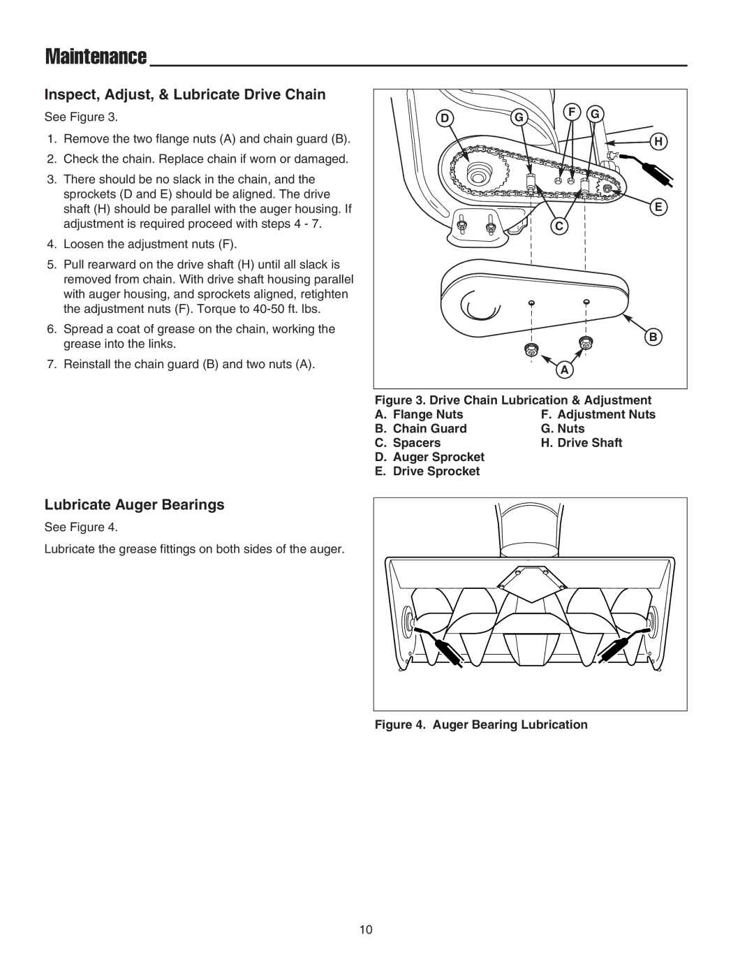
TROUBLESHOOTING
Troubleshooting, Adjustments, & Service
Electric Chute Rotator Gear
Troubleshooting, Adjustments, & Service
Drive Chain Adjustment
Skid Shoe Adjustment
IMPORTANT NOTE
Lift Rod Adjustment
Troubleshooting, Adjustments, & Service
Belt Tension Adjustment
Belt Replacement
Description
Initial Setup & Assembly
Figure 10. Initial Setup
Description
Install Skid Shoes
Initial Setup & Assembly
INITIAL SETUP & ASSEMBLY
Install Hitch
Initial Setup & Assembly
Install Chute Rotator Switch and Harness
Attach Deflector Control Cable Support Arm Assist Lever
Initial Setup & Assembly
Mount Remote Deflector Control
Initial Setup & Assembly
Install Snowthrower
4. Lift the snowthrower up fully and support with wood blocks
Initial Setup & Assembly
8. Route the drive belt as shown in Figure 23. Note that the back of the belt rides in the back-side idlers
Initial Setup & Assembly
Removal
Removal Normal Installation
Removing & Installing the Snowthrower
Normal Installation
Manual Lift Models
LIFT VARIATIONS WHEN USING ATTACHMENTS
Tractor Lift Linkage
Hydraulic Lift Models
Screw, 1/2
Torque Specification Chart
Hardware Identification & Torque Specifications
Nut, 1/2”
NOTE Read through instructions before beginning
Mounting Remote Deflector Control
MOUNTING REMOTE DEFLECTOR CONTROL
Line Template Up with Edge of Plastic Dashboard
Template
Line Template Up with Top Crease of Plastic Dashboard
Mark and Drill One 9/32” Hole
Template